| Resurrection Home | Previous issue | Next issue | View Original Cover | PDF Version |
Computer
RESURRECTION
The Journal of the Computer Conservation Society
ISSN 0958-7403
|
Number 103 |
Autumn 2023 |
Contents
| Society Activity | |
| News Round-Up | |
| Queries & Notes | |
| World’s First Beautiful Computer: IBM 360 Model 40 | Kevin Stumpf |
| Programming the Later EDSAC | Andrew Herbert |
| Obituary : Gordon Adshead | Bob Geaterell and Others |
| 50 Years Ago .... From the Pages of Computer Weekly | Brian Aldous |
| Forthcoming Events | |
| Committee of the Society | |
| Aims and Objectives |
Society Activity
|
EDSAC — Andrew Herbert For the past several months the EDSAC team have been working to improve the interface between Main Control (order fetch and decode) and the Arithmetic Unit. We had significant problems with getting signals correctly synchronised and with sufficient margin to tolerate the gradual decline in the performance of the thermionic valves we use, most of which are 70+ years old and have now been in use for 10+ years in the replica. A review of the design of the order decoding system, one of the first areas of the machine to be reconstructed, led to a number of improvements to the design and now the Arithmetic Unit is much happier with the signals it receives. During this same period we also suffered a lot of failures of EF55 valves. These are high output valves used to drive signals between the EDSAC racks. It seems they don’t like being left in the full on state for extended periods. As a consequence our stock of EF55s has fallen to a low-level (~30). With support from TNMoC we have been able to secure a further 115 “new old stock”, but our usual sources of supply report they don’t have any more squirrelled away. If any CCS members have a cache of EF55s, the EDSAC team would very much like to take them off your hands! To help ameliorate matters we have made some adjustments to circuits that use EF55s to try to reduce the loading on them in the hope that they will live longer. Having cleared these hurdles, our efforts now return to fully commissioning the Arithmetic Unit and the Transfer Unit. (The latter is concerned with correctly aligning long versus short number writes to the store).
The TNMoC “Tunny team” which is responsible for looking after the TNMoC exhibits relating to the German Lorenz Cipher (Tunny machine, Heath Robinson, Colossus etc) has kindly constructed and tested a photo-electric tape reader for us, working from a few seconds of images in the 1951 EDSAC video for their inspiration. The reader is mechanically driven and can run at up to 50 characters a second in stop-start mode which is in itself a technical tour-de-force. The control and reading system is appropriately constructed from period relays and valves. We hope to connect the reader to EDSAC a little later in the Autumn. We have also made progress on developing a diagnostic monitoring system based on modern microcontroller-based monitoring probes, known as “EDLAs” (ESP32 Digital Logic Analyser) that collect signals locally via a 16 channel interface and which can be interrogated via WiFi from a central RaspberryPi server where data is aggregated and archived for offline processing and analysis. A shared precision timestamp device is fed to each EDLA so that data sampled in one EDLA can be correlated with that in another. Presently three EDLAs are connected: two to the clock and digit pulse system and one to the main store addressing system. Generally the clock and digit pulse EDLAs are accessed via web interface to verify the clock and digit signals are present and appropriately spaced. The store addressing signals will enable monitoring of every read and write to store and the recirculation of data within the store, thus allowing us to monitor the reliability of the store and the store addressing system. In principle, seeing every read and write will allow a higher level analysis to verify that EDSAC correctly executes programs loaded into the store obeying orders in the correct sequence and that each order executed produces the expected result. If a failure occurs the monitoring system will detect it and analysis of the failure should help diagnose here the fault actually lies. A Raspberry Pi Pico version of the probe, imaginatively named “PEDLA”, is also under development. The EDLA/PEDLA probes were designed by Jeremy Bentham and are written up here: iosoft.blog/2022/04/11/edla/. The architecture is generic and not specifically tied to EDSAC, so may be of use to other projects. Jeremy’s design, schematic, PCB layout and software are all publicly available from the above link. |
)
|
Ferranti Argus/Bloodhound Missile System — Peter Harry Our Argus 700 based Bloodhound simulator was moved to the RAF Air Defence Radar Museum last January. Now it is open to the public for demonstrations of air defence during the Cold War. The demonstrations are carried out by a local team. The Launch Control Post containing the simulator has attracted a good number of visitors over this summer. We now have the challenge of maintaining the simulator from a considerable distance as the local team have no experience of the Argus 700, their skills lie with the earlier Ferranti Argus 200. When a fault occurs, the experience needed to resolve is a four-and-a-half-hour drive away from the museum at Neatishead in Norfolk. To date we have had one failure at the museum, now resolved, unfortunately resolution was delayed due to personal circumstances and the distance involved preventing a quick response. The Argus 700 based simulator is running again after fault finding revealed poor edge connector contacts and a possible defective co-processor (needs checking). The simulator uses three Ferranti Argus 700 processors a GX and two GLs. Maintaining the Argus 700 and other electronic assemblies that have been abandoned to the elements for twenty years provides for plenty of corrosion and oxidisation which continues to be our maintenance focus. To ensure a working future for the simulator we must be able to repair the PCBs that make up the Argus 700. We would like to test cards in situ, but we need Argus 700 extender cards, we do not have any. Did they ever exist? In fault finding the Argus 700 it has been found that a few TTL devices are prone to failure notably the 7438 (four-bit binary full adder with carry) among others. The latest challenge is to repair the Argus 700’s ½ Mbyte memory (16 bit) PCB, designed around 64K × 1 DRAMs.
An ME147 memory PCB test rig is now up and running to repair these and can identify individual faulty DRAMs. This photo illustrates the test rig in action, note the ‘home’ environment. The main components, connected with ribbon cables, in designing the test rig are:
The ME147 memory PCB includes a DP8400 error correcting device which allows for two faulty DRAMs before the PCB becomes defective in use. The result being that fault finding will identify three faulty DRAMs, obviously there are other faults besides DRAMs. Faulty DRAMs are usually found along the bottom edge of the PCB indicating the board has probably been handled without the use of an anti-static strap. We are always on the lookout for spares and currently in the process of repatriating faulty Argus 700 PCBs before they are sent for scrap. These PCBs could be repaired and/or will have irreplaceable Ferranti components that can be salvaged for spares. Additionally, we will repatriate a few Argus 500 assemblies for TNMOC and a couple of Argus 200 ‘peg’ program trays for another UK museum and a US museum. |
)
|
ICL 2966 — Delwyn Holroyd In July one of the DCU 5V 150A power supplies failed, the first failure we’ve had for quite some time. All previous failures in these supplies had been control board related, but this one was unusual – it was going into current limit at about 30A, five times lower than it should. These units have a pair of switching transistors that conduct on alternate cycles. The waveform on the current limit transformer showed that one of the two transistors was breaking down and conducting when it should have been off. This was causing a large current spike, triggering the current limit circuit.
The two driver boards containing the switching transistors are mounted one on top of the other, the upper transistor being the faulty one. After removing the upper board I discovered the lower transistor had a round burnt spot on the case – evidence of an arc having occurred at some point. I concluded there must have been a build-up of fluff in the gap that was sufficiently conductive to cause an arc from the collector of the lower transistor (which reaches 800V) to either the emitter or base of the upper transistor, thus damaging it. It should have been a simple matter of replacing the transistor, but it turned out TIPL777A power Darlington transistors are unobtainable via any of the usual sources, with no equivalent. However after a lot of searching I eventually found an Irish distributor specializing in obsolete components who were able to source TIPL777B, a higher specification version, albeit for an eye-watering price!
TNMOC has recently acquired a 1KW electronic dummy load, which allowed us to test the repaired supply at full load, something we haven’t been able to do before. |
)
)
|
Harwell Dekatron — Delwyn Holroyd Sadly we learnt WITCH user Tony Oakley passed in late June, aged 81. Tony used the machine in the late 1960s / early 1970s to teach coding when it was at Wolverhampton. He was a guest at the TNMOC “Grand Digital” celebration in 2018, where he regaled us with his many stories of the punched card era. We were also saddened to hear of the death of Peter Burden in 2020, aged 76. Whilst still a schoolboy, Peter and Mike Tedd were asked to write a program for the Chubb lock company to produce listings of valid lock combinations. A photograph of Peter together with then head of department Frank Hawley holding one of the program’s paper tape loops was published in the local paper. He went on to both study and work at the college. He was a guest at the Reboot in 2012, and at a gathering of former Wolverhampton users in 2013. The machine has been relatively trouble free since my last report, the only serious issue being the 50V power supply fuse blowing. There was no obvious cause and following replacement it has run without issue. Whilst we know the machine was on display at Birmingham Science Museum for some years, we didn’t have any photographs of it in situ. We have recently received a set of slides taken by Cecil Ramsbottom, one of the key figures at Wolverhampton responsible for the survival of the machine. The slides include many black and white close ups of the early days at Wolverhampton (including some before the WITCH nameplate was added), a complete set of circuit diagrams (which we have already in higher quality), but most interestingly colour shots of the machine at Birmingham. The latter are unfortunately undated, but the machine has a “Not in use” sign attached. It would be interesting to know how long it remained operational at Birmingham – we know from a letter sent by the museum to Dick Barnes in 1975 that the machine was then “ailing”, but we don’t know if it was successfully repaired. |
|
Software — David Holdsworth I can report that Dik Leatherdale and I are collaborating on reworking the online presentation of software and emulators on the CCS website. I think it fair to say that progress is in a good direction but less rapid than one might hope. Dik has already split software and emulators, but we view the current software page as embryonic and waiting for more input from me. I have come to the view that alongside the preservation of software, we should be looking at preservation of original documentation. There is a discussion document at ccsoc.org/hold0.htm My current LeoIII page has some of this philosophy, and can be seen at ccsoc.org/hold1.htm. |
|
Elliott 803, 903 & 920M — Terry Froggatt Peter Onion reports that the TNMoC 803 has been running reliably all summer (when it wasn’t too hot). However it has recently developed a couple of store faults which have led to some investigations of the +10V supply to the core store sense amplifiers. This is derived from a 13.5V inverter which has a rather large ripple on its output. The puzzling thing is that the ripple frequency is approximately six times the inverter switching frequency. This may be a coincidence, but there is nothing elsewhere in the machine that would explain this frequency. It is not known if this ripple has always been there, if it has just appeared or if it has been getting worse over the years. There are a number of 60 year old electrolytic capacitors in the inverter (and the following 10V regulator) which will be checked. Investigations will continue until the source of this ripple is understood. Peter Williamson reports that the TNMoC 903 also seems to be running OK. There are times when it stops when cold but normally a re-load of BASIC gets it running again and then it is OK. He suspects that there might be a problem with the PSU on the expansion chassis as he has heard the relay momentarily switch out. The fat +6V 15A fuse in this unit has been replaced with one of Andrew Herbert’s modified design. I have now finished “ringing through” the wiring of 920M MCM7 serial 5343, and I’ve checked this against 920M MCM7 serial 88. This flushed out a couple of errors on my part, but there were no differences. Given this complete but turgid database (of all component pins connected to a given signal), I’ve inverted this to draw clearer conventional circuit diagrams (all signals connected to given components). I’ve also produced a description of the LSAs (Logic Sub-Assemblies) used in the control and register decks, and a schedule of all of the external connector pin-outs. |
|
ICT/ICL 1900 — Delwyn Holroyd, David Wilcox, Brian Spoor, Bill Gallagher
Brian has partially recovered the subroutine library SGVP from the binaries of the various 1830 test programs we have, this is an ongoing sub-project. Brian has also been looking at the 1956 Data Disc Store, for which we have the sales brochure and some test/utility programs but no manuals. The implication from the software (#NFDA – disc test and #QDSS – Dump and Restore) is that there can only be a single ‘unit’, which may be made up of disc units on a single controller. There appears to be no individual unit identifier such as a cartridge serial number or similar. There is some disparity in capacity between the software and the sales brochure – the latter saying 31.5 MChs whilst the Dump/Restore and test software is programmed for a hard limit of 256 cylinders, with 128 sectors (60 words/sector) per cylinder, giving a capacity of 7.8MChs. The information from the brochure seems to match one of the Data Products 500 series discs. They appear to be for use with a 1904/1905/1909 and E4BM issue 4 (upwards). Were any actually sold? David has recently completed work to produce a master source for EDS DCPs and is now able to reproduce each DCP from that single source. The exercise has been useful in that it has shown how the different parts of the DCP interact with each other and just how much is actually common to all of them. Bill has obtained a new copy of FLIT, which has enabled him to find and fix several bugs in the emulator regarding the correct handling of reservation violations, which are not effectively documented in anything in our possession. He has also obtained NCR5, an exec mode test program that would be run prior to FLIT. NCR5 is a bootable tape that runs a set of very low-level tests in sequence, or, simply by positioning the paper tape in the long gaps on the tape, individual tests can be run. The tests assume much less is working than FLIT. Information wanted, if anyone can help:
|
|
IBM Museum — Peter Short
Our colleagues in Böblingen have sent us a replacement belt for our 029 card punch, and a spare punch clutch spring. The belt has been replaced, not without some difficulty. There’s a write up and photos at slx-online.biz/hursley/029-belt.asp. We are in a general discussion with TNMoC and The National Museum of Scotland about a potential System/360 display next year. |
)
)
|
Analytical Engine — Doron Swade The omission of regular reports is not indicative of a drop in activity. Quite the opposite. My last report signalled a turning point: Tim Robinson’s panoramic and detailed technical description of Babbage’s designs for the Analytical Engine put us in a position, for the first time, to specify what would be meaningful to build. In March last year I reported that we needed to expand the team to include expertise that we did not have – primarily solid modelling and mechanical engineering, and the report was an invitation, a call, a plea, for expressions of interest to take the project forward. We have had a promising response. Len Shustek, Chairman Emeritus of the Board of Trustees of the Computer History Museum, picked up the gauntlet and set about engaging with Tim’s technical description of the AE and assessing options for going forward. This exploratory collaboration has been a welcome relief to Tim who has been working for the last six years in near–complete isolation. Discussions are ongoing about the algorithms Babbage proposed for computational process, the prospective role of various forms of simulation, and criteria of authenticity in our design of apparatus where Babbage’s provisions are less than complete. Discussions are ongoing about how to finesse the balance between fidelity to the original designs and their practical feasibility. Moving to implementation invokes issues of funding, project management, intellectual ownership, and hosting the eventual build. Since the last report Tim has expanded the knowledge–base with an extended account of Babbage’s Mechanical Notation – his quasi-mathematical language of signs and symbols that he used to describe mechanisms and their operation. Tim’s description includes the historical development of the Notation and Babbage’s use of it in his engine designs, especially for the Analytical Engine about which practically nothing has been published. The account runs to 16,000 words which extends the length of the overall account to some 140,000 words, a treatise that ranks as a defining treatment to date of Babbage’s work on calculating machines. So the knowledge base is sound and provides an unprecedentedly well-founded platform for implementation. Just over 200 years ago Babbage wrote: Whether I shall construct a larger engine of this kind, and bring to perfection the others I have described, will in great measure depend on the nature of the encouragement I may receive. – (Charles Babbage to Sir Humphrey Davy, 3 July 1822). |
|
SSEM Replica — Chris Burton The Baby replica is now settled into a very consistent routine. There is a good team of volunteers, many of whom are newish recruits but who are progressing through training and familiarity with the machine and the context of the museum. All of them exude enthusiasm. As for the machine itself, there has been a particular persistent fault which has been present for many months, causing the machine to stop in a puzzling state. This happens unpredictably, sometimes several times a day, other times several days between occurrences. A number of diagnostic approaches remain in place to try to trap this elusive fault. It has little effect on visitor experience because visitors are usually more enthralled with the volunteer’s presentations than apparent unreliability of an “ancient” artefact. Another area beginning to be troublesome is the power supply system. Like other parts there is some concern about very long term sustainability issues while retaining adequate authenticity. The number of visitors remains high on average though daily numbers vary from not many to a recent group of 70. On the rare occasions when only one volunteer is present the machine cannot of course, be powered up. Nevertheless, visitors seem satisfied with the story and in any case there is often very good feedback complimenting the volunteers about their knowledge and enthusiasm. |
|
Turing Bombe — John Harper
The Bombe Rebuild Project commenced a little over 25 years ago. Throughout that period two supporters have and still do make parts using their skills, tools, and other items of their own machinery. One of these volunteers is STEVEN BROOKE. I presented him with a small plaque recently in grateful recognition of the tremendous contribution he has made to the rebuild project over a 25-year period. |
)
|
Delilah Voice Secrecy System — John Harper One of the sections we have not so far built is the wheel progression system. This is like a German Enigma machine where a wheel progression depends on whether a previous wheel indicates that it should progress. This is a complex mechanism with many parts adjustment screws and springs involved. We did not have accurate drawings and not enough detailed photographic information with which to produce new ones. GOOD NEWS:- With the help of Hanslope and a museum in the States, drawings have been produced from which parts have been made by Hanslope using 3D printing methods. This just leaves for us to make a simple lever mechanism that progresses the code wheels when the operator changes from receive to send. |
|
The National Museum of Computing — Aneesa Riffat We are working with the Reading Museum to co-produce an exhibition on DEC which will be in place next year. This has come about on the back of a successful joint bid to the Heritage Fund. |
News Round-UpIt is perhaps, not widely known that the costs of printing and distributing Resurrection are generously borne by BCS, the Chartered Institute for IT. In an era of rising costs, we have agreed to reduce the frequency of publication to three issues a year. 101010101 As so often, we have heard of the passing of several pioneers in the field of early computing. Peter Burden and Tony Oakley are mentioned in the WITCH report above and our good friend Gordon Adshead is remembered below. But we should add the name of Doug Comish, a LEO man who rose to head the International Division of ICL in the 1980s. the LEO Society’s Frank Land’s obituary for him can be found in The Guardian at ccsoc.org/comish.htm. May they all rest in peace. 101010101 Franny Corry of the IEEE Annals of the History of Computing has approached the CCS asking to be kept in touch with CCS events which may be of interest to her readers. Happy to report that she has joined the CCS and we look forward to a fruitful relationship. At a chance meeting last year at a Manchester computing conference [ed] and Martin Cooper editor of the BCS’s IT NOW publication established another co-operative relationship which has already borne fruit. |
|
Jim Miles, who is diligently cataloguing lots of early Manchester photos, would like to know what the device is. It seems to be part of an electro-mechanical device at the back of one of the racks of the 1949 Manchester Mark I computer and is thought it may be something to do with a 5-track paper tape reader. If you can help please contact Simon Lavington (och@computerconservationsociety.org). 101010101 If anybody knows of an emulator for an analogue computer running on modern hardware (ideally under Linux) please contact the editor who will pass the information on to an enquirer. |
)
|
The 50th anniversary of the announcement of a family of computer systems was celebrated on the 7th April 2014. Journalists wrote about the “beauty” of the idea, the architecture, and the implementation, and touted the many achievements the S/360 would be known for, but they missed something and it was staring right at them. Let’s stop peeking inside the machine. Close the doors of the frames, cabinets, and walls, and start recognising the beauty of the face, skin, and figure of the S/360. It would be easy to find writings admiring the innards of computers. It would not be unusual to see the admiration expressed as “art” and as “craft”. Yet, mostly, the art and craft of computing technology is unseen. Who can see electrons? Nearly everyone has ignored what can be seen with the naked eye. The S/360 is simply a family of bizarrely attractive machines. There is not only an art and craft of the machine, in the case of the S/360, the machine is art and craft. Knowing whether the S/360 executed instruction pre-fetches or not doesn’t have the same initial and lasting impact as the fetching colours, materials, and forms of all S/360s.
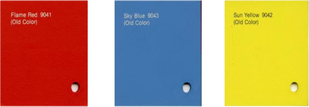
By the time IBM decided to move forward with a new line of computers, IBM Industrial Design teams everywhere were poised to present what we now know as the System/360. You could not buy a grey S/360. You chose between Flame Red, Sky Blue, and Sun Yellow (see ccsoc.org/ibmcolours.jpg). There was the consistent S/360 design across all processors and peripherals, and there were the iconic control panels that were slightly different for each model, but similar enough to instantly identify the computer as a S/360. Without further ado, envelope please! And the world’s first beautiful computer is: the IBM System/360 Model 40 (/40). In IBM parlance, Machine Type 2040. In April 1965, just a year after being announced, the first S/360, a /40, was delivered to a customer. This put the spotlight on the /40 so one could argue the extensive use of the /40 to promote the System/360, and perhaps computers in general between 1965 and 1970, was the result of being first IBM 360 out of the gate, but I hope to show you that even as the forerunner of the S/360 movement, it earned the title as the first beautiful computer ever. First S/360 delivered; first beautiful computer. Are you wondering why the plain and simple word “computer” is being used instead of “mainframe”? The reasons are twofold: to be historically accurate and to be comprehensive. So, since the word “mainframe” wasn’t popular until the 1970s I have not used it when referring to a computer announced at least six years prior. Plus, the scope of computing hardware includes not only mainframes, that is big computers, but all dedicated computing machines such as desktops, laptops, and supercomputers. Any computer can be beautiful. All I am saying is that the /40 was the first. The way some people describe the taste of food or wines or “interpret” paintings, makes me giggle. At least though there are vocabularies bona fide by gourmets, sommeliers and critics. Not so when it comes to describing big old computers. “Oh Model 40, how do I measure thy beauty? ” Too much? The industrial design community has the language. Me? I would simply say the /40 possesses an unexpected artistic quality that resonates with my sense of good taste, and earns my respect by obviously being well thought out. Every S/360 product has class. Here was a machine that, in each installation, formed a community of machines (line printers, tape drives, card readers, drums, etc.), because of their familial resemblance. Here was a machine – a machine! – that could easily fit the décor of an art gallery. What a machine! Sleek, colourful, coordinated, and, just the right size. I shall now begin my Goldilocks-rant. You see the /20 isn’t really a S/360, the proportionality of /22s and /25s, especially the size of the control panel on the /25 is not appealing, but while the size of the /22 has merit it was released almost as an afterthought in 1971 so it had knobs replacing the classic white and black “flipper” switches, and the knobs were plastic unlike the proud, shiny metals ones used on /40s. The /30 is problematic size-wise, but that goofy control panel put it out of the running, the /44 – too tall with a stark control panel. The /50, /65, and /67 are impressive, but enormous, too big. Then there’s the gigantic /75 and /85 (besides the /85 had a console instead of a control panel which made it too different), and finally the gargantuan /91, /95, and /195, all just too vast. The /40 is just right.
The /40 was the first S/360 out of the gate, but it remained the most photogenic model even years after all the S/360 models had been delivered to customers, which says something. The /40 was featured on the covers of all sorts of magazines and books. Also, IBM used the /40 extensively in promotional material from the 1964 until 1970. Why did IBM use the /40 when all models were available? Because it was the most beautiful product out of the whole bunch.
Of course, since the /40 was the first model available for showing-off, it was the focal point of an incredible exhibit in the downtown New York city showroom. A poster of the showroom was included in the Movement collection of art teaching aids published by Van Nostrand Reinhold. Neon lighting swirled around the windows that enclosed a handsome, svelte /40 computer system. Deservedly so.
The /40 also appeared in a revolutionary article in Cosmopolitan. You could not pick up many newspapers or magazines between the years 1965 and 1969 without seeing a /40. It was a star of print. Life magazine used the /40 in a spectacular fold-out. Companies of the era used computers to identify as being hip. Hollywood loved the /40 too. It was the centrepiece of several movies.
Beauty doth rest in the eye of the beholder, but I am not the only one who thinks the /40 is beau monde. In 2007 I introduced an artist to a friend of mine who had a /40 control panel. The artist gathered precise measurements of the control panel to use to sculpt one out of metal. Here is the original gorgeous control panel and the resulting exquisite sculpture.
The overall beauty of computers floundered, to me, after the /370 family (which was mostly a copy of the S/360). IBM is making a comeback though. The daring and novel, monochrome (black), but still classy, IBM z13, z14, z15, and z16 mainframes, and the stunning IBM Quantum System One. Looks like we’ve come full, 360° circle. Starting with the IBM System/360 Model 40 as the world’s first beautiful computer and now declaring the IBM Quantum System One as the next beautiful computer. Bravo IBM! |
)
)
)
)
)
)
)
)
)
)
)
)
)
)
)
)
)
)
Programming the Later EDSACAndrew HerbertIntroduction Most of the literature about EDSAC describes the machine as it was when first operational in 1949, and in early use as a computing service at Cambridge from 1951 onwards. The principal reference is the first edition of the Wilkes, Wheeler and Gill book, “The Preparation of Programs for an Electronic Digital Computer” published by Addison-Wesley in 1951. This book is essentially a programming manual for the early machine. The EDSAC replica under construction at TNMoC implements exactly the 1951 machine and, indeed, all the various EDSAC emulators the author knows of also implement this version of EDSAC. However, during the life of the original EDSAC there were significant updates to the machine architecture and order code, and to the circuits, as the Cambridge pioneers explored new ideas and learned from user experience. The architectural and order code changes were described in a booklet, published by the Cambridge University Mathematical Laboratory in 1955, entitled: “Introduction to Programming for the EDSAC” – A supplement to “The Preparation of Programs for an Electronic Digital Computer’ by Wilkes, Wheeler and Gill”. The same material was later included in a 1957 second edition of Wilkes, Wheeler and Gill. A copy of the “Introduction to...” booklet was recently donated to the EDSAC Replica Project by Gillian Lindsey, from the estate of her late father, Charles Lindsey, who will be fondly remembered by many Computer Conservation Society members. Gillian told me that the booklet originally belonged to her mother, Sylvia Lindsey (neé Rossiter) – and, as Gillian told me: “my parents met at the [Cambridge] University Mathematical laboratory in 1950, where Dad was a PhD student and Mum was a Hollerith operator. They both worked on the EDSAC.” Reading the booklet, I thought a concise description of the architectural and order code changes made to EDSAC in its later life might be of interest to Resurrection readers. EDSAC Overview The Electronic Delay Storage Automatic Calculator (EDSAC) was built at Cambridge University and ran its first successful program on 6th May 1949. By early 1951 it was providing a computing service to users across the university. The team that created EDSAC, led by Maurice Wilkes, saw EDSAC as an experiment. In Wilkes’s own words, written for Volume 1, Issue 2 of Resurrection in 1990: “It [EDSAC] was not a project to build a computer only. It was a project to build a computer, to learn how to use it and then to solve some problems. The machine was to be simple with no frills, except that it was to be comfortable to use. I didn’t want it to be the sort of machine that the user had to know about pulses inside it or timings and so on. There was to be no attempt fully to exploit the technology. Provided it would run and execute programs, that was enough.” In the event EDSAC proved very successful, remaining in service until 1956, when it was replaced its successor, imaginatively named EDSAC 2. As Wilkes said, EDSAC was a simple machine with no frills: just 1024 × 17-bits of main store and a repertoire of only 18 instructions. Input was from paper tape and output to a teleprinter, later a paper tape punch. EDSAC was intended as a machine for scientific computation: there was no hardware floating point arithmetic, users computed with either 17-bit fixed point fractions, so called “small numbers” or 35-bit “long numbers” occupying two consecutive storage locations (an extra bit being available when store was addressed in this way). The programmer had use of a 70-bit accumulator register, and a 35-bit multiplicand register. Arithmetic was twos complement. There were other internal registers, e.g., the Sequence Control Tank (or program counter in modern terms) but these were not directly accessible from programs. Unusually for the time, EDSAC programmers wrote their code in symbolic rather than in binary form. Programs were loaded under the control of a hard wired “initial orders” routine that read in tapes punched in alphanumeric form and converted them to the hardware binary form. EDSAC was a single address machine: orders took the form of a function code, an operand address and a “special indication bit” to flag whether a small or long number arithmetic was required. Function codes were written as a single character such as A for add, S for subtract, the less mnemonic N and V for multiplication and so on. Operand addresses took the form of a decimal number in the range 0-1023. Small number operations were flagged by the letter F following the address, long number operations by the letter D. Thus, a typical order might be written S 102 D, meaning subtract the contents of locations 102 and 103, treated as a long number, from the accumulator. If an order referenced address 0 this could be omitted, as in e.g., Z F. For some orders, such as the shift instructions L and R, the address field was a literal, indicating how many places to shift left or right. In orders that did not perform arithmetic, such as the G and E jump instructions, the “special indication bit” had no significance (but this was to change later...). The symbolic code embodied many other useful features including relative addressing, dynamic linking and control codes to guide the placement of master programs and subroutines in store, and to kick off execution, but it is not necessary to delve into these to understand the evolution of the EDSAC order code over time. As we will discover, in the early days there were a few chinks in the hiding of the binary form of numbers and orders – it was necessary for programmers to know the function code was in the top five bits of an order, followed by a spare bit (that turned out to be very useful later on), then ten bits of operand address and finally the special indication bit. In the following sections we report the various architectural and order code changes made throughout the life of EDSAC in the light of operational experience and developments elsewhere. Address Modification In the original EDSAC there was no direct provision for writing loops that indexed through a sequence of store locations (e.g., a vector). The programmer was forced to modify the orders comprising the loop to increase (or decrease) operand addresses to access successive elements of the sequence. Writing self-modifying code in this way was error prone and costly in valuable store locations, especially in a loop doing arithmetic over several vectors. Typically to modify a single operand address took four orders (clear accumulator, add in order to modify, add increment and put back in store). Moreover, the programmer had to understand the binary format of orders and know that to increment an operand address in an order it was necessary to add 2-15 (2-16 being the special indication bit). A new order M (“Mix”) was added to simplify this process. M n F clears the six most significant digits of the accumulator and then add the contents of location n, C(n), into the content of the accumulator, C(acc). The net effect is to replace the function and spare digits of C(acc) by those of C(n), and then to add the address digits of C(n) to those of C(acc). Typically C(n) was the template for the order to be modified and C(acc) the index value. While the M order removed the need for the programmer to understand the binary representation of orders, indexing still required a sequence of several orders to modify the addresses of each indexed order in a calculation. A better solution came with the introduction of the B-register. The B-register The concept of a B-register (i.e., index register) and B-modification (i.e., address modification) originated at Manchester. Following the Manchester concept, the EDSAC architecture gained an additional, “B”, register. The previously spare bit in the order format was used to specify if address modification of the current order was required. In consequence the spare bit became to be known as “the B bit”. If the B-bit was set, the contents of the B-register are added to the operand address field modulo 1024 to compute the effective address of the order. In written programs the B-bit can be set by adding 1024 to the operand address field of an order, there being no checking of the address value by the initial orders. Thus A 1034 F (i.e., A 1024+10 F) adds the contents of the location with address C(b)+10 modulo 1024 to the accumulator, where C(b) is the content of the B-register. A suite of new orders was added to manipulate the B-register: B m F to replace the content of the B-register with the number m (N.B., not the content of location m); J m F to jump to location m if the content of the B-register is non-zero, otherwise continue serially; and K m F to write the order B b F (where b is the content of the B-register) in location m. The use of B and J is obvious and K provides a convenient way to copy the B-register to store for reloading later in a calculation, e.g., when indexing several vectors at the same time, or saving the B-register before entering a subroutine that itself uses the B-register. Because address modification is calculated modulo 1024, a “negative address” -m can be loaded into the B-register using an order of the form B 1024-m F. Incrementing and decrementing the B-register is possible using address modification on the B-order itself. For example, B 1025 F (i.e., B 1024+1 F) adds 1 to the B-register. Decrementing the B-register further exploits the fact that address modification is calculated modulo 1024: BS 1023 F (i.e., BS 1024-1 F) will subtract 1 from the B-register. Thus, with these new orders, programs can walk up or down a stored vector by manipulating the B-register, obviating the need for self-modifying code. Expecting the programmer to do arithmetic on operand addresses was thought inconvenient so some new notation was invented. Following the function code letter with the letter “S” (for “spare”?) sets the B-bit, as in AS 200 F which adds the contents of location C(b)+200 to the accumulator. Following the operand address with an “S” (for “subtract”) replaces the address with its complement modulo 1024. Thus AS 200 S adds the contents of location C(b)-200 to the accumulator. Applying this to the B-order, BS m F says increase the content of the B-register by m and BS m S says decrease the content of the B-register by m. Programmers who wanted to use this notation in their programs were required to load a special subroutine R30 before any part of their program. R30 threaded itself into the copy of the initial orders loaded into bottom of the main store, adding the code required to detect the two uses of S and decode them appropriately. Programmers were advised to load R30 at the top of store (locations 1014-1023), space that could then be freed up for workspace once the program was fully loaded. It was not possible to include R30 into the hard-wired initial orders encoded on uniselectors due to a lack of space and would have upset other conventions about the use of locations at the bottom of the main store. To economise on the use of store all the library routines written by the Mathematical Laboratory eschewed the use of the S notation. Jump Orders The original EDSAC had just two jump orders: E – “jump if accumulator is positive (greater or equal to zero)” and G – “jump if the accumulator is negative”, both essentially a test of the accumulator sign bit. As soon as one starts to learn EDSAC programming it quickly becomes apparent that it would be useful to also have an unconditional jump and a jump if the accumulator is zero. If the programmer could predict the sign of the accumulator before an unconditional jump was required then they could use E or G as appropriate; if not one could always write a sequence such as E 123 F G 123 F, but that wasted a location of precious store. (Or a T order could be used to clear the accumulator, then followed by a E, but this too wasted a location of store for the T order and also there had to be a destination where the contents of the accumulator could be dumped (T n F means “copy content of accumulator to location n and then clear the accumulator”). In the later EDSAC, the F order, previously associated with teleprinter output (see below) was repurposed as an unconditional jump. F n F unconditionally transfers control to location n. With the advent of the B-register, the need to test for zero to end a loop counting up or down, or indexing through vectors was dealt with through the new B and J orders. But, if the zero test was required on the result of a calculation, originally this had to be coded a sequence of orders: negative results could be ruled out with a G, then subtracting 2-16 followed by a second G would branch if the positive value had indeed been 0.0. This issue was addressed by adding a second variant of the new F order: F m D (i.e., F with the special indication bit set) jumps to location m only if the accumulator was non-zero. The special indication bit was also given a meaning for the G and E orders: G m D clears the accumulator if the branch is taken, whereas G m F leaves the accumulator undisturbed. Similarly for E m D and E m F. This expedient shortened typical loop order sequences. Subroutines In the early EDSAC subroutines were entered by a construction called “the Wheeler Jump” named after its inventor, David Wheeler, at the time Wilkes’s research student. A typical entry sequence in store would look like:
    3    U2F      Useful constant in Initial Orders
         ...
    100  TOF      Clear acc - not needed if acc already zero
    101  A101F    Load this order's bit pattern into acc
    102  G200F    Jump to subroutine entry
    103  ...


    200  A3F      Subroutine entry point - convert C(acc) to E order
    201  T220F    Plant in return link
         ...
    220  ZF       Becomes E103F
On entry the caller loads the accumulator with the bit pattern of an A order with the current address and jumps to the first location of the subroutine (200). A G (jump if negative) order is used because the bit pattern of the letter A (the function code) is 11100, i.e., -4 and therefore negative. After the introduction of the F order as a jump, the order in location 102 could instead be written as F200F. At the start of the subroutine, the order A3F adds the bit pattern of the order U2F to the bit pattern of A101F, producing E103F which is then planted as the last order of the subroutine, here in location 220. Provided the accumulator is zeroed before this order is obeyed, the effect will be to return from the subroutine by jumping in this case to location 103. (An E order is generated rather than an F unconditional jump order because location 3 containing U2F is part of the initial orders and was fixed long before the F order was changed to be a jump.) The ZF in location 220 is just a sentinel – should the subroutine be executed other than through its entry sequence, for example in the event of a programming blunder, the ZF instruction will halt EDSAC and ring the bell, rather than allowing the program to run further amok. With the introduction of the B-register, and redefined F order, a simpler entry and exit sequence became possible: . . .
101 B101F Load address of this order into B-register
102 F200F Jump to subroutine entry
103 . . .
. . .
200 K220F Subroutine entry point - save B-register in location 220
201 . . .
. . .
220 ZF Becomes B101F - load value 101 into B-register
221 FS2F Jump to 103
The K order at the start of the subroutine places the bit pattern of the order B b F in location 220, where b is the content of the B-register, i.e., 101: if the subroutine does not use the B-register for its own purposes, the K order is not required and only the FS2F order is required in the exit sequence. The initial EDSAC library subroutines used the first approach and were known as “closed A subroutines”, those using the second, as “closed B-subroutines”, and were the approach recommended in the booklet for user-written subroutines. Input-Output Initially input to EDSAC was from a mechanical paper tape reader and output to a teleprinter. Both were slow devices and an operational bottleneck. They were replaced by 1951 by a 50 ch/sec photo-electric tape reader and a paper tape punch. Output was printed (on a teleprinter) offline. The EDSAC designers were concerned about the possibility of errors arising in numerical output – as EDSAC was designed for scientific computation output consisted mostly of tables of numbers. In the original machine, for the convenience of programmers, the digits 0-9 were represented internally by their numeric value. This meant of course that a single bit error could easily corrupt a digit and lead to incorrect output. This was addressed by the F order. F m F read back the character set up on the teleprinter mechanism in response to a preceding O (output) order and stored it in location m. Output routines could thereby verify that the character to be typed was indeed the one intended. Late in 1951 this output code was discontinued and a new code adopted in which two and only two of the possible five holes were punched for decimal digits, +, - and space. Thus, if an error arose, the symbol punched was likely to be other than a decimal digit. Since the probability of a compensating double fault arising was considered extremely small, the new code provided a reasonable level of protection against errors and the F order became available for other purposes –namely the unconditional jump described above. Overflow Detection The original EDSAC lacked any form over overflow detection on the accumulator. An early design document – “The EDSAC Report” – discusses the possibility of halting the machine at an overflow, but it was realised that, particularly when arithmetic functions were being used for their logical function, overflow was a side-effect rather than an error. Later, a scheme was added to allow the programmer to detect overflow and take action. This was achieved by introducing a new order “Ά” (EDSAC included some Greek letters in its input alphabet) and adapting the pre-existing Y or rounding off order. Y F remained, as in the original EDSAC, the rounding-off order, rounding C(acc) to 34 binary digits. The orders Ά n F and Ά n D transfer C(acc) to location n (as a short number for F or long number for D) and clear the accumulator. If an overflow has occured after the accumulator was last fully or partially cleared, the machine is stopped, an “accumulator overflow” lamp lit on the operator control panel and an audible warning given. The operator could then perhaps load a diagnostic tape, or perhaps make a note of the values of registers from the display unit and then restart the machine to continue execution, having cleared the overflow indication. If, instead, the programmer wanted to take control, the Y m D order could be used. If there had been an overflow since the last occurrence of a Y m D order, the accumulator would be cleared and C(m) taken as the next order; otherwise, execution proceeded serially. There were some anomalies with the overflow orders: a false overflow indication would be given if a multiplicand of -1 was used when the multiplier register contained a negative number; nor would an overflow indication be given if the number -1 was subtracted from a positive (fractional) quantity contained in the accumulator. Telephone Dial As originally built EDSAC lacked any means of interactive input – it was envisaged as a batch processing system, but with experience it was realised it would be useful to have post-mortem routines to dump out selected areas of store and some means was needed to input the starting and ending addresses of the blocks to print out. A telephone dial was added for this purpose. The interface was very simple: if the machine was stopped (i.e., by a Z F order), rotating the telephone dial would add the value of the digit dialled into the top five bits of the accumulator and then resume execution at the next instruction in sequence. An amusing use of the telephone dial was in an interactive noughts and crosses (tic-tac-toe) game. The board was displayed on the storage display cathode ray tube, using 1s (shown as bright dots) and 0s (shown as dim dots) to show the grid layout and move taken. Each square in the grid was numbered and when it was the user’s turn, EDSAC would halt waiting for the user the claim their next move using the dial. Conditional Break Stop The behaviour of the Z order was modified to take account of the special indication bit: Z m F stops the machine and lights the “program stop” lamp on the operator control panel. This was the conventional way to halt a program, either because it has completed, or for an operator intervention, such as loading a new paper tape, inputting via the telephone dial or manually single stepping execution. Z m D by contrast only stops the machine if a special “ Z D” switch on the operator control panel is set. In other words, Z m D is a conditional “break stop” order for help in diagnosing mistakes in programs. The operand address has no meaning in either case. The conditional stop order is only described in the second edition of Wilkes, Wheeler and Gill (1957), but not in the booklet of 1955. This might suggest it was a very late addition to the machine? In the early EDSAC the Z order also rang a bell to attract the operator’s attention. It is unclear from the documentation whether or not this continued to be the case throughout the life of the machine. Magnetic Tape Auxiliary Store The booklet also mentions further orders added to enable the use of magnetic tape as an auxiliary but the details are incomplete and “not intended as a description of how to use the magnetic tape system”, suggesting that at the time the booklet was written, 1955, the auxiliary store was a work in progress. Interestingly there is no mention of the auxiliary store in the later (1957) second edition of Wilkes, Wheeler and Gill, further suggesting the auxiliary store was at best experimental and possibly never completed. After writing this article I found some more details about the magnetic tape system in some of the reminiscences recorded at the EDSAC99 conference in Cambridge to celebrate the 70th anniversary of the machine running its first programs (ccsoc.org/and0.htm). These tell of a simple interrupt like mechanism to allow computation to proceed in parallel with seeking data on a tape. Conclusions The changes made to EDSAC throughout its life show that much of the original design was satisfactory – only one order was replaced (order F to verify teleprinter output). Others were extended to meet user experience (M to simplify indexed loops, F n F to add jump if zero, G D and E G to clear the accumulator on a conditional jump, Z D to introduce conditional break points and the Y D and Ø n F / Ø n D orders for handling numeric overflow). Cambridge was also willing to adopt ideas from other places, in particular the B-register and address modification concept from Manchester. More dramatic changes were made when the Cambridge team designed EDSAC 2. EDSAC’s successor had many features derived from lessons learned from the construction and use of EDSAC as a practical computing service for the university. |
Obituary : Gordon AdsheadBob Geatrell and others
Gordon was a stalwart of the NW group of the CCS for many years, acting as our secretary from 2010 to 2018. His organisation skills and contacts were second to none, having been honed in so many environments during a full life. Even recently, he’d turn up at meetings or apologise profusely if he couldn’t make it due to a clash with another of his numerous interests. He was never one for a quiet life. He was born in Didsbury in 1940, attended Manchester Grammar School, before going to Pembroke College in Cambridge to gain his degree in Mechanical Science. But he was fascinated by those new-fangled electronic computing devices and took a job back home with Ferranti at West Gorton in 1962. He moved into and eventually ran the Design Automation team, helping designers to get their messy thoughts organised to document, build and test increasingly complex systems. Through Gordon, ICL’s Design Automation team and skills became well known across the world, with Gordon regularly attending and chairing international conference and editing papers for the learned journals. Young Gordon was always in a hurry. He’d race one of his colleagues out of the office after work, which on one occasion had him crashing through an unnoticed glass door and ending up in hospital. He revelled in his unusual surname and its homonym of “+Z”, which he regularly used as his signature. Unsurprisingly, a few of his DA contacts in the States were nonplussed by the “Plus Zee”. Thanks for everything, +Z. A lot of people are going to miss you. A lot. |
)
50 Years ago .... From the Pages of Computer WeeklyBrian AldousBP to use Argus 500s for oil work: Monitoring of off-shore oil production in BP’s North Sea Forties Field concession is to be handled by a duplex Ferranti Argus 500-based system worth £250,000. To be installed at an operations centre in Dyce, near Aberdeen, the two Argus 500s will each have 32K of core store and two Megabytes of disc backing store. The system will supervise drilling operations and control the flow of oil in the seabed pipeline to Cruden Bay, some 20 miles further up the coast, and the on-shore pipeline to Grangemouth where oil is either refined or shipped at the new deep water tanker terminal in the Firth of Forth. The operations centre will have alarm and data logging facilities, a plant mimic diagram and CRT monitors with colour displays for tabular and graphic information on the state of the remote plant on the off-shore platforms and pipelines. (CW 6/9/73 p1) PDP-8 users benefit from new system: : A new programming system announced by Digital Equipment, will, for the first time, allow users of their PDP-8 minicomputers to compile and run programs in ANSI standard Fortran IV. Known as OS8 Fortran IV, it is run under Digital’s OS-8 operating system. The Fortran software, comprising a compiler, assembler, system loader and run-time system, is available at a cost of £350. It will run on a minimum configuration comprising an 8K PDP-8 under OS-8, a console and two DEC-tapes. The entire hardware-software package is priced at approximately £5,700. The ANSI standard Fortran package provides many facilities not included in the previous Fortran system available on the PDP-8, using Fortran II. Among these extra capabilities are run-time format specification, and handling of arrays of up to five dimensions on the minimum configuration, with generalised subscripting. Format errors at run time, according to Digital, are notified by clear English statements, and debugging facilities are provided, allowing the logic path terminating in the erroneous statement to be traced. Virtual memory facilities are available, in addition to a powerful overlaying capability, and Digital claims that it is possible, using OS-8 Fortran IV, to run programs occupying as much as 10 times the real memory capacity of the machine environment. (CW 13/9/1973 p9) Am-Ex now looks at credit card terminals: As in most spheres of data processing the US appears to be leading the way in the development of on-line computerised credit card authorisation systems. American Express, for example, is at present evaluating a retail-type terminal called “Amcat”, manufactured in the US by Addressograph-Multigraph Data Systems, which can be installed in shops, hotels and restaurants and which is designed to read the magnetically encoded credit cards now held by all Am-Ex users in the US. Am-Ex customers at outlets using Amcat have their account number read from their card and transmitted automatically to an Am-Ex mainframe computer system at the local authorisation centre. The amount involved is entered via a keyboard on the terminal and if the computer authorises a transaction Amcat automatically prints a receipt for the customer. (CW13/9/1973 p27) GEC moves into the cash card market: The magnetic money company, Revenue Systems, set up with £80,000 worth of NRDC and TDC capital four years ago, has been acquired by GEC-Elliot Automation, part of the GEC empire. Earlier this year the company had been declared insolvent after struggling for several months to make its first user system, installed at a self-service garage in Reading, operational. The business, set up to exploit the potential of a cash card the value of which could be magnetically encoded on the card and electronically altered after each transaction, was placed in the hands of the receiver and negotiations began with several interested companies. GEC had been attracted for some time by the possibilities of magnetically encoded cards and by the movement towards cashless money systems and the company was well aware of the potential in this area. At present the big oil companies are embarked on a large investment programme in self-service garages in a bid to slash operating costs, and the Revenue Systems card-operated pump could easily fit into this programme. At large manned stations, the number of cars handled could be greatly increased by converting some of the pumps to self-service operation. Motorists using the garage could then buy a cash card at a discount and use it to unlock the pump. The value of petrol taken would be automatically debited and the motorist could use the card until its value was exhausted. At smaller country stations such pumps would permit unmanned operation at night to provide 24-hour service. (CW 13/9/1973 p48) Marconi’s new radar displays: Greater detail of visual information is now obtainable with two new types of radar display announced by Marconi Radar Systems. The S3016 can display live information in three different colours, red, amber and green, and the S3018 incorporates a rear port through which a colour film of maps or charts can be superimposed on live radar. The 3016 incorporates a display screen with two phosphor layers, one behind the other, the front one showing red and the rear green. By varying the anode potential the speed of the electron beam can be adjusted to illuminate either layer or both to give amber. According to Marconi, a live radar scan can be divided by computer into three groups covering friendly aircraft, enemy aircraft and alphanumeric descriptive data, and then displayed on the 3016 screen in three colours. The 3018 display incorporates an optical projection system which can hold over 1,000 separate 35mm frames of film. (CW 20/9/1973 p9) EMI looks to voice data input market: Foreseeing a growing market for voice data input systems, EMI, the £300 million-a-year electronics giant, has signed a letter of intent with a small US firm which has specialised in this area, Threshold Technology of New Jersey. The two companies plan to set up a joint enterprise in Britain in the near future. This company is intended “to market over much of the world electronic systems for recognising spoken words and converting them into signals for controlling machines or instructing computers”. EMI will hold 60 percent of the equity of the new company, which will be headquartered in Hayes, Middlesex. The letter of intent also requires EMI to make a cash investment of $1.2 million (£480,000) in Threshold, in return for which it will acquire just under 25% of the equity. The new company will begin by marketing Threshold’s voice recognition systems in the UK. These identify spoken words and convert them into digital signals. A major selling point is that they can eliminate a lot of paperwork. (CW 20/9/1973 p40) PoS report predicts big market: Both manufacturers and potential users of PoS retail terminal systems will be interested in a 200-page report on the European PoS market now available from Frost and Sullivan Ltd, of The Strand, London. The report predicts a market worth over £800 million for PoS equipment in Europe over the next 10 years and is the first survey from the new European subsidiary of Frost and Sullivan Inc, who have published many reports in the US on the computer industry. The report points out some basic differences between the European and US retailing methods that could affect the design and marketing of PoS equipment. One difference is that credit card sales are of little importance in Europe, especially in France and Germany, two of the major PoS markets, so that credit verification features are not really needed. The report, which costs about £160, covers virtually the whole of Western Europe.. (CW 27/9/1973 p16) Character Reading Wand: A hand-held wand for reading printed eye-readable characters may be available soon from Recognition Equipment of Dallas, Texas. Industry sources indicate that a prototype wand has already been shown in Europe to certain long-term potential customers. The most promising application could be in the booming PoS market. RE in the UK is unable to comment as yet about the wand and there is no indication yet of when it will be officially announced or how much it will cost. It appears, however, that development is quite well advanced since it is believed that the prototype model can read the numeric and special characters of the OCRA and Farrington 7B stylised founts. Characters are read by a photo diode array chip at the tip of the wand and some of the character recognition and coding circuitry is located in the wand body itself. Interfacing would simply involve incorporating a single additional PC board in the main body of the terminal using the wand. (CW 4/10/1973 p1) More versatile PC system from GEC: Manufacturers looking for a more versatile process control system than hard-wired relays or solid state networks will be interested in a programmable logic controller system developed by GEC-Elliott Process Automation Ltd. The system offers a number of general purpose computer features without accompanying cost and employs a programmable read-only memory, PROM, which can be programmed on-site if required by any process engineer with an appreciation of logic and Boolean arithmetic. The PLC system incorporates inputs and outputs in up to 47 groups of 16 per card and can operate at over 100,000 instructions a second. Each instruction is made up of 16 bits, five for the function and 11 representing the address. There are 11 “bit” instructions, each of which operate on a particular input/output bit, nine “word” instructions and seven “jump” instructions. Up to 2,048 of these instructions can be held in the PROM in modules of 32, on cards holding up to 512. Each module comprises a group of integrated circuits each of which consists of a matrix of fusible links. Programming involves the fusing of certain of these links to create a string of binary bits, 0s and 1s, representing instructions and locations. (CW 4/10/1973 p25) In-store PoS system goes live: What Singer claims to be the first complete in-store PoS processing system to go live at a British department store is now in operation at Garlands of Norwich, part of the Debenhams group. A 48K Singer System Ten in the store receives and processes data continually from 38 Singer MDTS retail terminals which handle sales in all 53 departments. The System Ten at Garlands includes an 8,000,000 character disc store and a workstation which allows management to access sales data relating to any of the 53 departments at any time of the day. At the end of the day the System Ten produces more detailed reports showing sales for each department broken down into cash and credit sales. Overnight the system produces complex cash analyses for each terminal and indicates stock shortages and surpluses. It is understood that Garlands intend later to use the System Ten for on-line credit sanctioning, with credit account numbers on disc, and to introduce magnetically encoded price tickets for automatic product data capture using the Singer 710 tag reader. (CW 18/10/1973 p1) Europe’s MADAP system goes live: The first section of the Eurocontrol air traffic control system, MADAP, covering upper air space over Belgium and Luxembourg, has gone live on schedule. MADAP also covers the northern part of West Germany and Holland, and the Hanover sectors of that stage are due to come into operation next spring. MADAP, Maastricht Automatic Data Processing, is being built by a tri-national European consortium which includes Plessey. It was conceived in 1964 when the seven nation Eurocontrol upper air traffic control agency decided to set up the centre. The consortium, consisting of Plessey Radar, AEGTelefunken, and Thomson-CSF, looked into the anticipated patterns of air traffic in the Seventies, and as a result of their findings, was awarded the Maastricht contract, along with Eurosystem SA, a joint subsidiary set up by the three companies. (CW 15/11/1973 p1) DEC takes up the OEM challenge: In a move designed to strengthen further its position in Britain’s increasingly competitive OEM market, Digital Equipment has announced three new versions of the PDP-11 minicomputer, a high density 16K memory for the PDP-11, and a new low-cost version of the PDP-8. The new products, which have been made possible largely as a result of Digital’s development of new memory systems, may be seen as a response to announcements by other minicomputer manufacturers such as Interdata and Computer Automation, who have introduced processors at the upper and lower ends of the minicomputer spectrum respectively, for use by original equipment manufacturers. Digital’s top end offering includes two OEM versions of the PDP-11/40. The larger of these, the 11/35F, starts with 32K words of the new high density memory at a cost of £10,800. Plug-in 16K modules of the new memory can be added on to bring the capacity of a single configuration up to 128K. The smaller version, the 11/35J, starts as an 8K machine costing £4,900 and can be expanded in 8K increments to 128K. The third new PDP-11 is an expanded version of the 11/05. This is now available in a 10½” rack-mountable cabinet with 8K words of memory expandable to 28K. Using the same processor as the standard 11/05, the new-version contains a number of additional facilities including pre-wired connector slots for extra memory and communications interfaces. A further item of new equipment in the PDP-11 range is the 16K high density memory unit which is used in the 11/35F. This unit, which has a 980 nanosecond cycle time, comprises a single planar stack which, claims Digital, enables twice the amount of data to be stored in a third more space. The new memory enhances the cost effectiveness of PDP-11 systems and, at £2,320 for an add-on unit, is claimed to about half the price of a conventional 16K memory. The remaining DEC introduction is a low-cost version of the PDP-8, known as the PDP-8/M, which has already been introduced in the US. This minicomputer, which features a combination of programmable read only memory, PROM, and read/write memory, comes in two versions with 1K and 2K memories, respectively. Both are available as single units, or to manufacturers in quantities of 100, at £909 for the 1K model and £1,552 for the 2K model. (CW 22/11/1973 p1) Nimrod contract won by Ferranti: A contract to supply computers to the Ministry of Defence for the Searchwater radar system to be used on Nimrod maritime reconnaissance aircraft has been placed with Ferranti’s Digital Systems Division by EMI Electronics, manufacturers of the radar. The order is worth about £500,000. The machine selected is an airborne version of the FM1600D, a computer derived from Ferranti’s F1600 series which are, in turn, silicon transistor derivatives of the Hermes range launched in 1963. The FM1600D –the “M” stands for micro-miniature – uses MIS (Medium Scale Integration) and Ferranti’s own high density eight-layer printed circuits. (CW 22/11/1973 p48) Floppy disc drive launched by Calcomp: A new floppy disc drive, the CDS 140, has been announced by California Computer Co, Calcomp. It rotates faster, at 360 rpm, and has a larger capacity, three million bits, than Calcomp’s existing CDS 110 drive, and is expected to appeal to a much wider range of customers. The CDS 140 is media compatible with IBM and can be made format-compatible if the user wishes, though this reduces the storage capacity to two million bits. Thus the media has 77 tracks and 26 sectors and a record size of 128 bytes, and the transfer rate is 250,000 bits per second. The CDS 140 has a track-to-track access time of only six milliseconds and a head settle time of 10 milliseconds, a performance claimed by the com-pany to be considerably better than on any other drive yet produced. The CDS 140 has been designed for heavy duty applications, which Calcomp defines as meaning an average of one sector read and one seek every two seconds throughout a 40-hour week. With this sort of usage the company is claiming an MTBF of 5,000 hours and a minimum error rate of one in 100 million. (CW 20-27/12/1973 p8) |
Contact details
Readers wishing to contact the Editor may do so by email to
Members who move house or change email address should go to
Queries about all other CCS matters should be addressed to the Secretary, Rachel Burnett at secretary@computerconservationsociety.org, or by post to 80 Broom Park, Teddington, TW11 9RR. |
CCS Website InformationThe Society has its own website, which is located at www.computerconservationsociety.org. It contains news items, details of forthcoming events, and also electronic copies of all past issues of Resurrection, in both HTML and PDF formats, which can be downloaded for printing. At www.computerconservationsociety.org/software/software-index.htm, can be found emulators for historic machines together with associated software and related documents all of which may be downloaded. |
Forthcoming EventsMembers and others are welcome to attend CCS Seminars but these are also available via Zoom. London Seminar Programme
London meetings take place at the BCS — 25 Copthall Avenue Moorgate EC2R 7BP starting at 14:30. The venue is near the corner of Copthall Avenue and London Wall, a three minute walk from Moorgate Station and five from Bank. You should use the BCS event booking service to reserve an in-person place at CCS London. Go to www.computerconservationsociety.org/lecture.htm . The service must be used for remote attendance. For queries about meetings please contact the CCS meetings secretary, Roger Johnson at meetingssec@computerconservationsociety.org Manchester Seminar Programme
Manchester meetings normally take place at The Manchester Metropolitan University, Chester Street, Manchester, M1 5GD – Room E0.07 in the John Dalton East Building starting at 18:00. Details are subject to change. Members wishing to attend any meeting are advised to check the events page on the Society website. MuseumsDo check for Covid-related restrictions on the individual museum websites.
SIM : Demonstrations of the replica Small-Scale Experimental Machine at the Science and Industry Museum in Manchester are run every Wednesday, Thursday and Friday between 10:30 and 13:30. Admission is free. See www.scienceandindustrymuseum.org.uk for more details. Bletchley Park : daily. Exhibition of wartime code-breaking equipment and procedures, plus tours of the wartime buildings. Go to www.bletchleypark.org.uk to check details of times, admission charges and special events. The National Museum of Computing At present opening days are somewhat irregular so see www.tnmoc.org/days-open for current position Situated on the Bletchley Park campus, TNMoC covers the development of computing from the “rebuilt” Turing Bombe and Colossus codebreaking machines via the Harwell Decatron (the world’s oldest working computer) to the present day. From ICL mainframes to hand-held computers. Please note that TNMoC is independent of Bletchley Park Trust and there is a separate admission charge. Visitors do not need to visit Bletchley Park Trust to visit TNMoC. See www.tnmoc.org for more details. Science Museum : There is an excellent display of computing and mathematics machines on the second floor. The Information Age gallery explores “Six Networks which Changed the World” and includes a CDC 6600 computer and its Russian equivalent, the BESM-6 as well as Pilot ACE, arguably the world’s third oldest surviving computer. The Mathematics Gallery has the Elliott 401 and the Julius Totalisator, both of which were the subjects of CCS projects in years past, and much else besides. Other galleries include displays of ICT card-sorters and Cray supercomputers. Admission is free. See www.sciencemuseum.org.uk for more details. Other Museums : At www.computerconservationsociety.org/museums.htm can be found brief descriptions of various UK computing museums which may be of interest to members. |
North West Group contact details
|
||||||||||||
Committee of the Society
|
||||||||||||||||||||||||||||||||||||||||||||||||||||||||||||||||||||||||||||
Computer Conservation SocietyAims and ObjectivesThe Computer Conservation Society (CCS) is a co-operative venture between BCS, The Chartered Institute for IT; the Science Museum in London; the Museum of Science and Industry (MSI) in Manchester; The National Museum of Computing in Bletchley and the Bletchley Park Trust. The CCS was constituted in September 1989 as a Specialist Group of the British Computer Society (BCS). It thus is covered by the Royal Charter and charitable status of BCS. The aims of the Computer Conservation Society (“Society”) are:
Membership is open to anyone interested in computer conservation and the history of computing. The CCS is funded and supported by a grant from BCS and donations. Some charges may be made for publications and attendance at seminars and conferences. There are a number of active Projects on specific computer restorations and early computer technologies and software. Younger people are especially encouraged to take part in order to achieve skills transfer.
|


