| Resurrection Home | Previous issue | Next issue | View Original Cover | PDF Version |
Computer
RESURRECTION
The Bulletin of the Computer Conservation Society
ISSN 0958-7403
Number 58 |
Summer 2012 |
| Editorial | Dik Leatherdale |
| Society Activity | |
| News Round-Up | |
| Misplaced Ingenuity | Hamish Carmichael |
| The ICS Multum as I Remember it | Bill Findlay |
| More Software from Lineprinter Listings | Dik Leatherdale |
| Programming in Schools -Your Letters | |
| Forthcoming Events | |
| Committee of the Society | |
| Aims and Objectives |
Resurrection
Happily Resurrection 57 seems to have been produced without any attendant printing or distribution problems. We are working closely with the BCS to try to ensure that such incidents never again darken our door.
Many thanks to the readers who took the trouble to get in touch about Resurrection's “new look”. I am pleased to report that feedback has been very positive. It has been suggested that underlining URLs and email addresses can confuse spaces with underlines, so that will cease. Jerry McCarthy has given me a solution to the problem of printing very long URLs which, to be honest, nobody is ever going to copy-type. tinyurl.com provides a redirection service for URLs and I will use this as the occasion demands in future. In reply to all those who have asked, the font is MS Reference Sans Serif 11 with a 16 point line spacing.
Heroic Failures
The serendipitous theme of this issue seems to be heroic failure. Powers Samas devised some of the most sophisticated punched card machinery going - much of it too late in the day to be viable in the marketplace. In the end its adherence to electro-mechanical technology forced the business into a merger with its deadly rival BTM. But Hamish Carmichael's description of some of its later technology surely cannot fail to impress.
ICS on the other hand, had the right product at the right time, but simply failed to gain the momentum which might have allowed it to take off. Indeed, it pretty much failed to gain any momentum at all! As a result it became the British computer company which almost nobody knows. I came across Bill Findlay's mention of it on his website and recognised his name from David Holdsworth's progress reports. Bill and I, unknown to one another, both worked with ICS - but I'd be surprised if many other CCS members have even heard of the ALP range, let alone seen one.
Correction Corner
Michael Kay rightly points out that ASCII is not an international standard - the “A” gives it away - and that it only extends to 128 characters anyway. “iso-8859-1” was what I had in mind. And who am I to argue? More grovelling then.
Committee Changes - Dik Leatherdale
Several changes to CCS's committee have taken place since the last edition of Resurrection. Most importantly, Hamish Carmichael has resigned from the committee owing to his impending return to his native Scotland. CCS Chair Rachel Burnett paid tribute to Hamish: “As Chair since last October, I have known Hamish only a short time, but long enough to appreciate what a lot he has done during his 16 years on the committee which he joined in 1996 as Secretary, taking on the role of Archivist in 2005. Future researchers will benefit hugely from Hamish's labours in organising the artefacts of the history of computing which are so important to understanding the development of computing in the UK. I would like to thank Hamish on behalf of everyone in the CCS, and wish him well in his retirement. We sincerely hope he will keep in touch”.
To which I should also like to add my own thanks to Hamish for his invaluable support of Resurrection over the years.
David Hartley assumes the role of Archivist and Doron Swade has volunteered to take on responsibility for the distribution of the Annals of the History of Computing.
Chris Burton is now fully engaged with the EDSAC Replica project and has handed on responsibility for the Elliott 401 to Rod Brown.
Finally, the Society now has responsibility for the Tony Sale Award which it treats as a “project”. Peta Walmisley is project leader. She is welcomed to the committee.
Tony Sale Award - Peta Walmisley
At a meeting on 15th March, attended by Brian Oakley as Chairman of the panel of judges, David Hartley, Kevin Murrell and myself, the composition of the judging panel and the criteria for assessing and judging entries, with the nomination form, were agreed.
Brian Oakley has contacted the potential judges and is waiting to hear from them. The call for nominations will go out at the beginning of May, to museums in the UK, USA, Netherlands and Germany; as well as to the IT History Society; IFIP and CEPIS and their member societies (with some personal contacts), including the BCS; IEEE CS for the Annals of Computing; and BBC websites. Suggestions for additional targets would be helpful.
The closing date for nominations will be 31st July 2012.
EDSAC Replica - Andrew Herbert & Chris Burton
We have principally been active on organisational matters, marketing and volunteer initiation.
A project Dropbox has been set up to contain all the project engineering, management and in due course, marketing documents. All the historical documents and photographs collected by Martin Campbell-Kelly and Chris Burton have been collected into the Dropbox alongside Chris's growing set of hardware notes and associated engineering documents. This is working more efficiently than the previous KnowledgeTree system although, being a file replication system, it is exposed to user blunders. Fortunately there is good versioning and back up.
Jointly with Chris Burton, the project manager has begun drafting work definitions for the initial activities of the construction phase. The first milestones have been set as 'pulse, counting, storing' - i.e. a working clock pulse generator and digit pulse separator followed by a half-adder and then store address decoding, a memory tank and storage regeneration circuit. Completing these milestones will mark considerable progress into the details of the machine design.
We have been investigating a project display stand at TNMoC to establish a presence for the project ahead of erecting the machine itself.
In terms of progress on the design, Chris Burton has been trying to establish some circuit design principles. In particular the design of the flip-flop has been troublesome. As a check of the design a complete section of a Flashing Unit comprising an AND gate and a flip-flop has recently been constructed on a breadboard chassis, tested, and indeed exhibited. As a result of the experiment some more work on the design will be needed. Other circuit work includes an initial look at the design of the half-adder and associated 'reversing circuit' or inverter.
Considerable time has been spent specifying and negotiating for heater transformers, and testing a supplied sample. A first batch of 20 has been obtained. Similarly, enquiries and options for tag strips have been made and documented.
The Logic Simulator has been rewritten in Java for greater portability and is now called ELSIE: (Edsac Logic SImulator and Editor). While testing ELSIE against the logic developed last year, Bill Purvis found a couple of minor errors which have been corrected. The program is now complete.
The next priorities are to get volunteers started and provide them with components and tools as required, finalise the display stand and work with staff at TNMoC on the interpretation of EDSAC as a museum exhibit.
EDSAC Replica Briefing - Dik Leatherdale
To TNMoC at Bletchley Park in March to attend a briefing for recruits to the EDSAC Replica project. Andrew Herbert, Chris Burton and Bill Purvis spent a happy afternoon telling 10 potential volunteers all about the EDSAC Replica project, describing the progress so far and the challenges ahead. I confess to being impressed, not just by the work done and planned but by the quality of the discussion amongst the volunteers. Success is, I think, assured.
 |
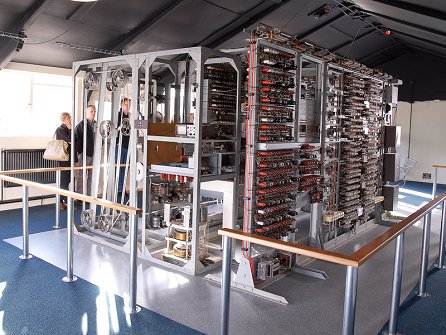
Whilst there, we were shown round the museum. I was blown away by the Colossus room. Final touches were being made to its makeover. The public will now have the opportunity to examine it from every angle which brings the display to life. If you haven't seen Colossus before, go now. If you have, go again! It's a revelation!
Elliott 401 - Rod Brown
Some time ago, we became concerned that the drum might deteriorate if it continued to be subjected to periodic power on/off cycles. It was decided that, as a matter of expediency, it would be a good idea to have the option to simulate the drum using modern technology. This would leave the original device in-situ but would allow the rest of the machine to operate with the drum powered off. As a bonus the horrendous noise of the operating drum would cease to be a problem.
The drum emulator is now almost complete and awaits in-situ testing when permission to start work on the machine is granted. A proposal for this work at Blythe House is with the museum.
Software Conservation - David Holdsworth
Edinburgh's IMP programming language was developed out of Atlas Autocode (AA). As part of this development, the Edinburgh team did a port of AA onto KDF9. The resulting compiler has been preserved in the Edinburgh archive.
Two of us (Graham Toal and I) are working on resurrecting the AA port. We thought it would be an easy job, as tapes had been digitally preserved in Edinburgh's history archive. Sadly, only the source text was preserved, not the binary program which would have made the whole thing a fairly straightforward application of our KDF9 emulation. However, Graham and I have set about recreating the binary program from the source, which is written in Atlas Autocode. So when we have it working we have a ready-made substantial test program. (Graham Toal is ex-Edinburgh and now lives and works in the US. We have never met.)
At sw.ccs.bcs.org/CCs/KDF9/AA.html there is a web page introducing this work. Near the foot of this page is a question that has so far baffled the team members, who wonder if anyone out there can provide enlightenment. The grammar contains two lines in the definition for a machine instruction -
'*' '‘' IDENTIFIER actual_parameters
'*' '@' IDENTIFIER actual_parameters
Both these structures exist in the compiler source, and both seem to imply the placing of the address of the AA variable into the KDF9 register. At present I am treating them identically though this may not be correct.
And so to other matters. We were delighted to hear from one Gustavo del Dago of Buenos Aires who is working on an emulator for the Ferranti Mercury. He has connected a paper tape reader which he hopes to use to load a paper tape containing the binary form of Mercury Autocode.
And, if that wasn't enough, following the articles about Autocode in Resurrection 57, Alan Taylor has made contact with us to report his development of a Sirius emulator which, one day he hopes, will be able to run a copy of Sirius Autocode.
Bletchley Park
As you might expect, there is much celebration of Turing's 100th anniversary in 2012. At Bletchley Park a new permanent exhibition opened in March.
Harwell Dekatron - Johan Iversen & Delwyn Holroyd
At the end of last year we discovered the oil filled transformer in the rectifier unit had started to leak. Our options were to replace the transformer with a modern one, remove all the oil and have the case opened, cleaned, re- sealed and re-filled, or attempt to stop the leak with an externally applied filler. We chose the last since it didn't preclude going back to either of the first two options, and the second option presented significant risks both to health due to the likely poisonous nature of the oil, and of irreversible damage to the transformer. We quickly discovered there were multiple leaks, most probably due to fissures opening up in the original soldered joints. Re- soldering wasn't an option without first completely removing the highly flammable oil, and we eventually used an oil resistant Araldite to seal all the soldered joints. This has been 99% successful but a couple of areas still require another coat.
The next job was to diagnose a suspected fault in the stabiliser unit with one of the valves glowing cherry red without any load on the supply - an indication of the valve being over-stressed. This was traced back to a failed metal rectifier in the rectifier unit. This unit contains quite a tour of rectifier technology with other metal rectifiers already having been replaced with more modern components throughout the machine's life.
The problem with replacing old components with modern equivalents is that the modern ones tend to be much more efficient which can have knock-on effects elsewhere in the circuit. To get around this, resistors have been added to compensate but final sizing of these can only be done when we know the load the machine will draw from the supply. We also added a load resistor to one of the supply outputs that is often unloaded in the normal operation of the machine, both to safely discharge the filter capacitors and to prevent the voltage across them rising to a level exceeding their rating, this latter problem being compounded by the more efficient modern rectifiers.
The two power supply units have now been successfully bench tested into dummy loads for a number of hours over several weeks. When we looked at the stability of the outputs in more detail we discovered a small wander on one of the outputs, which will probably prove to be due to a dirty connection or pot.
With working power supplies we moved on to the pulse generator unit. Tony Frazer had already cleaned this unit and done a lot of component testing, so after some more checks and safety tests on the heater transformer the next step was to apply power. We wired a spare connector to enable the unit to be connected to the main power supply on the bench. This has been nicknamed the 'Connector of Doom' due to the 13 high voltages between -385V and +370V DC it carries, not to mention AC mains!
The pulse generator, as its name implies, generates various pulse trains needed to step the Dekatron tubes and drive other electronics in the machine. We had expected the timing might have drifted due to component values changing with age - many of them being over 60 years old - but to our surprise the oscillator is running and generating 1.5ms pulses with a cycle time of 4.5ms, just as it is supposed to.
Using a test rig consisting of a few switches we have now been able to test most of the functionality of the pulse generator. The major issue so far has been trigger tubes, but we do now have trains of 10 pulses being generated and the Dekatron in the pulse generator itself is stepping correctly.
Eddie has cleaned and adjusted several relays which had been causing intermittent problems. He is about to commence safety tests on the HT rack wiring.
SSEM - Chris Burton
The replica continues to be regularly demonstrated on Tuesdays and Thursdays, though the number of volunteers has fallen off leaving a greater burden on those remaining.
Effort over the last several months has been devoted to improving the cathode ray tube stores, the raison d'être for the SSEM. The two-line control tube and one-line accumulator have been quite reliable for many months. To the credit of the volunteers and their persistence and patience, the main store tube is now working well enough to run many programs. An attempt to change the tube for a spare was also successful, implying that there is a growing understanding of how to set up the many parameters.
To explain the context for this work, it must be remembered that in 1998 the main store deteriorated, and under pressure to keep the machine demonstrable operation was usually based on exploiting the alternative semiconductor store. The availability of expert volunteers who were happy to come in to work at the museum on Thursdays has provided the opportunity to concentrate on repair and maintenance.
Elliott Project - Terry Froggatt
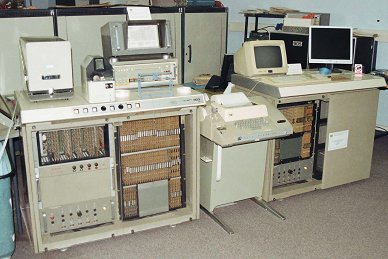 |
The battery managed to power the 803 for about five seconds when the yellow phase failed recently. However it blew a fuse in the process. Investigation of the circuit powered by the fuse was inconclusive.
A noisy fan has been serviced and is now running quietly again.
Plans are now being made to build a teleprinter driver for the paperless tape station as a precursor to building an authentic logic board to drive a teleprinter.
During February, many of the cards from the 'scrap' 903 were cleaned up and tested off site, and these were used to track down the fault in the 'good' 903. This was on an A-ED3 store address-wire driver card, so the corresponding card from the scrap 903 was substituted.
In March, a fault with an address key on the control console was located and cured, which was making it difficult to trigger programs at low addresses. Problems with the teletype & VT220 were traced to a faulty (modern!) printer switch, which was replaced.
The 903 then ran its test programs and BASIC successfully.
Atlas@50
This coming December sees the 50th anniversary of the inauguration of the Ferranti Atlas 1. Readers with an interest in Atlas should keep 5th December free in their diaries. A celebration in Manchester is planned at which a series of lectures on the subject will be given by those involved. More in the next edition of Resurrection.
ICL 2966 - Delwyn Holroyd
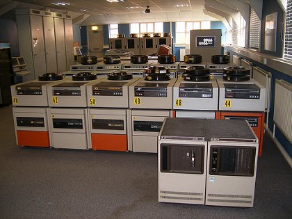 |
Work is almost complete on the firmware to support the new interface PCB in its rôle as a peripheral interface. I have successfully printed to the lineprinter using the interface and booted the machine from it.
I hit an unexpected problem interfacing the board to the DCU. It uses modern surface-mount RS-485 transmitters to drive the DCU, which are theoretically electrically compatible. However the load presented by the DCU receivers was such that the fancy protection circuitry in the transmitter chips interpreted it as a fault on the cable and promptly shut down! This was eventually solved with pull-ups to get around the high capacitance of the DCU receivers. I have repaired three card reader store boards using replacement RAM. These have been soak-tested on my test rig and in the card reader itself. Work is just commencing on the mechanism control boards.
The machine itself is currently non-operational due to problems with the ribbon cables between the store and SCU or, more particularly, some of the connectors. We have some spares which will be fitted when time permits.
ICT 1301 - Rod Brown
The ICT 1301 project restarted on 9th March 2012. The combination of problems we encountered at switch on have included a mill problem, a CPU instruction decoding problem and a section of core store (one fifth of the random access memory) missing. All this means we did not declare a working machine this year until it was agreed on 6th April that enough of the machine functioned for us to do so. Further problems with ageing test gear means we have had to invest in a replacement oscilloscope to continue fault finding.
Over the winter period the project acquired a second Elliott paper tape reader which was an eBay purchase, the first spare we were able to locate after many years of searching. After a few faults were removed it is now functioning well and confirms the cost and effort to obtain it were worthwhile. Some work will be required to modify our paper tape reading station to allow both read heads to be selected by software and then both heads will be online.
We have also had a power supply burn up (shades of Pegasus) which failed with smoke and damaged components. Fortunately spares were to hand and the power supply is up and running again. 2012 being the 50th year of the machine we will celebrate on the next public open day on the 8th July.
The interest of the local U3A organisations continues with further enquires about visits in 2012 and we have set a possible date of the Friday 10th of August for a group visit of the Bromley U3A. We have also been approached about a general presentation about British Computer History, which could work well with the Alan Turing events.
As usual all updates are online at www.ict1301.co.uk/1301ccsx.htm.
Analytical Engine - Doron Swade
The Science Museum has released the digitised images of Babbage's Analytical Engine drawings and notebooks to us under licence for purposes of study and research. Delivery of the disc with just under 7,000 images was taken on 20th January. Preliminary review indicates significant new material and also some alarming incompleteness in the drawings specifying the machine. The immediate task is to assess the degree of completeness of the original designs and to focus on the areas requiring significant new interpretation. In parallel with this, exploratory discussions are under way about the prospects of using simulation to test logical and mechanical feasibility. Having access to a digital archive is a major boost to the project given that daily return trips to the physical archive held at the large object store in Wroughton are prohibitively time-consuming and costly.
The material is now being studied for insights in to Babbage's designs. In parallel with this a study has been made to reconcile four conflicting classification systems used to reference the material since 1889. Consultation with the Science Museum archivists is underway to resolve the remaining uncertainties.
The second major activity has been fundraising and we are encouraged by initial responses.
North West Group contact detailsChairman Tom Hinchliffe: Tel: 01663 765040. |
The Science Museum has announced an award of £6,000,000 from the Heritage Lottery Fund towards its new gallery Making Modern Communications which, as we have previously reported, will have a substantial computing content and is set to open in autumn 2014. Making Modern Communications will tell the story of 200 years of innovation in communication technology and how we connect and share information with each other. The gallery will display around 1,000 objects of historical importance, many of which have never been on public display before. Congratulations to our good friend Tilly Blyth who led the funding bid.
Congratulations too on the news of her promotion to Keeper of Technologies and Engineering. Happily, her new post encompasses her previous responsibility for computing so she is not lost to us.
In the more immediate future, an exhibition celebrating the life of Alan Turing opens on 21st June and will run for a year.
-101010101-
GCHQ at Cheltenham has been presented with a pair of Enigma machines first employed by the German and Italian forces during the Spanish Civil War. The machines lay undiscovered for many decades before coming to light in Madrid. One of the machines has been forwarded to Bletchley Park. See www.bbc.co.uk/news/magazine-17486464.
Still with GCHQ, two of Turing's research papers, Paper on Statistics of Repetitions and The Applications of Probability to Crypt concerning the mathematical basis of his codebreaking methods were published in April. Apparently they no longer represent a threat to national security. See www.bbc.co.uk/news/technology-17771962.
-101010101-
At www.npl.co.uk/famous-faces/alan-turing is a short film about Turing's contribution to Pilot ACE by CCS members Tom Vickers and Mike Woodger.
-101010101-
Readers of a certain age will remember the Commodore 64, in its time the most popular computer in the world with total sales of 22 million. They will be saddened to learn of the death of Jack Tramiel founder of Commodore. After his ejection from the company he founded, he went on to lead Atari for a decade before retirement. Obituaries can be found in the usual publications gizmodo.com/5900742/the-anti+steve-jobs-dies being my favourite. Kevin Murrell was interviewed on BBC Radio 4's Last Word programme.
There have been many developments in the history of computers which have come to nothing. But the Powers Samas company seems to have had more than its fair share. I will touch fairly lightly on a number of machines that never made much of a stir in the world. There is no chance of the Society ever undertaking to preserve them, even if surviving examples could be found - but I think they are still worthy of the Society's brief attention. They all come from within the Powers Samas tradition. I was a part of that tradition, having joined in 1958. Three of the machines I will cover I have operated, and for two of them I have written programs - so they are old friends. I was always fascinated and delighted by the mechanical complexity of Powers machines. Not Babbage himself could have achieved such elegant intricacy. They were, in a way, the apotheosis of the purely mechanical. But they were the last of their line.
Universal Printing Counting Sorter
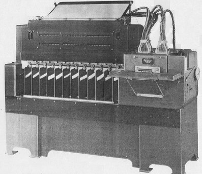 |
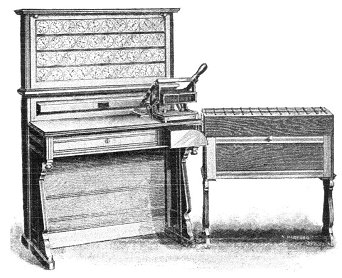
This first machine I never met. The picture shows the version of the machine that was used in the analysis of the 1951 UK National Census.
The basis of the machine was a conventional punched card sorter: the cards are fed from a hopper at the right hand end and distributed into twelve receiving pockets corresponding to the twelve positions in one column of a card. And of course there is a reject pocket for any cards which are blank in the column being sensed. However, the superstructure of the machine is entirely special.
Unlike a conventional sorter there are two sensing stations instead of one. The upper part of the beast contained the counting and printing mechanism. There were 36 five-figure counting units arranged across the width of the machine in three banks of 12. Each bank also had a six figure counting and printing unit at its right hand end, keeping a cross-added total of all the 12 counters in its bank. And at the extreme right hand end there was a six figure counting and printing unit which counted all the cards processed in the run; so its total was equivalent to the sum of the three bank-total counters to its left. Finally at the extreme left there was a five figure printing unit (no counting this time) to print a designation which would identify and distinguish each line of print. That meant that there were 209 character positions in each line of print.
On the front of the counting complex there were visible indicator wheels showing the values being accumulated in each counter. The picture also shows that the counters were in fact double-deckers. An impulse received from a card would operate both levels of the relevant counter. But when a total was taken, the lower rank of counters was zeroised after printing; the upper rank was not. The higher level totals accumulated in the upper stage could be printed and cleared by the operator pulling down a hand lever.
The paper control and printing mechanism was fairly straightforward. It could handle continuous paper but continuous paper thirty inches wide was not a common commodity, so most printing was done on separate sheets.
On the input side there were two sensing stations, with sensing units that could be positioned over any column of the card. The first station had one unit controlling sorting, and up to four controlling automatic totalling. The total control columns did not have to be adjacent. The total control sensing units were also the source of the designation information printed at the left hand end of each line of totals.
The second sensing station had three sensing units, each of which could be connected to one of the three banks of counters in the top of the machine. All these connections were made by Bowden cables. All the cables were individually detachable, so that each position in a card column could be connected to any counter.
In fact later versions of the machine had a sort of multiplexing unit between the sensing stations and the counters. An example of the use of this was to enable counting by age groups, not just by individual ages.
 |
The machine ran at 400 cards per minute, but the actual throughput depended on the frequency of totalling, because printing a total took a time equivalent to nine card feeds
One of the things that strikes me about it is that the functionality is remarkably similar to that of the machines devised by Herman Hollerith for the 1890 census in the USA. The flexible connections between card positions and counters were the same. The combination of counting and sorting was the same. There were two crucial differences: the movement of the cards was automated, and the results of counting were automatically printed.
The PCC. or Programme Controlled Computer
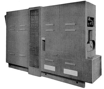 |
Well, it certainly had a programme - which hadn't yet lost its final 'me' - by which it was controlled, but calling it a 'computer' was perhaps going a bit far. It wasn't a full computer in the sense that the Society understands - where the program is itself held in store and may be modified during running.
But then, Powers Samas was not aiming to achieve a completely general purpose computer in the modern sense. What it wanted to create was a machine that could take its place in the work of a conventional punched card installation. Its predecessor the EMP - or Electronic Multiplying Punch - was limited to multiplying (with a little bit of cross-adding thrown in). By contrast the P.C.C. was much more flexible.
But when Powers Samas and the British Tabulating Machine Company merged to form ICT, and a common way of identifying both product ranges by type number was established, the P.C.C. was given the type numbers 556 and 557, which places it firmly in the same category as the BTM calculators - 542, 550 and 555.
To programme one of those calculators you were given a fixed number of programme steps, and at each step you had to plug the function to be performed, the source position of one or two operands, the paths by which they were to be accessed, the destination of the result, and the path it was to follow, plus sundry niceties. It could be quite challenging to get all of them right.
By contrast a programme for the P.C.C. was much like a program for a proper computer. Admittedly the number of program steps was still limited, but each step was much simpler - just choose the right function code and specify the operands
Physically the P.C.C. was quite a big beast - twelve feet long, six feet four inches tall, and nearly three feet from side to side. It weighed a heck of a lot.
The last time I saw one was about two years ago, in one of the old hangars at Wroughton. It was the machine which ran accounting systems for many years for Swindon Council. Now it had been split down the middle, mounted on two pallets, and one half was the wrong way round. A sorry sight it was.
Since it was a punched card machine it is logical to start with the detail of its workings with the card track. The magazine into which the input cards were placed was at one end, immediately under the operator's control panel. The receiving hopper was half way along one side.
Reading and Punching Units
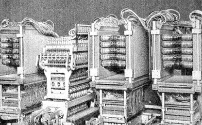 |
The cards were fed through two successive sensing stations and so each card was read twice. The results of these two readings were compared, and if there was any discrepancy between them the card was rejected. It's not possible to ask the designers why they included this feature, but my guess is that it was a symptom of a typically Powers Samas distrust of all this electricity stuff. A quote from the brochure: “Reading and punching - Mechanical, therefore positive”.
The data from a successfully read card was then distributed into the store through an application-specific mechanism - similar in principle to the connection box in a Powers tabulator. While the program was being obeyed the card moved forward to the punching station and, when the program was complete, the results were punched into it. It then passed to another reading station, where the results actually punched into the card were compared with the results computed by the program. A card which passed this test was then ejected into the receiver. Any card which failed either test - after the second reading or after punching - was inverted before ejection.
There's the story of the two inexperienced operators left overnight to put a long run through the P.C.C. who decided that these inverted cards looked a bit untidy, so they turned them all right way up. When the supervisor came in next morning: “What, no errors?” was her first remark. Better forget what she said next.
The Store
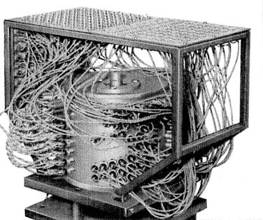 |
The store, for data only, was on a magnetic drum and was arranged in six tracks: one for input, one for output and four for main storage. Each track could hold 40 words, and each word could contain 16 digits in either decimal or sterling form. In addition, there were six fast access stores interposed between the main store and the arithmetic unit, but they were also somehow incorporated into the drum. I can't remember how this was done, and the documentation rather skates over it without giving any detail.
The literature says sniffily: “The P.C.C. does not use the binary scale of notation but performs arithmetic directly in the familiar decimal and sterling scales. This is one reason for its high operating speed.”
The Programme Board
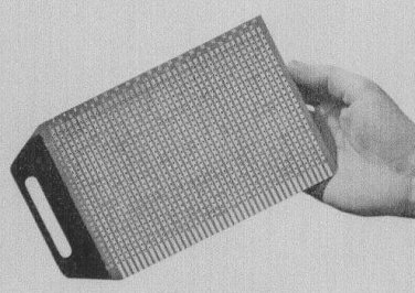 |
Now we come to the unique feature of the P.C.C. - the method of inputting the program to the machine. The program could consist of up to 160 steps. These were input on four programme boards, so each board could hold 40 steps, each step being represented by a transverse row of holes. Into the appropriate holes were fixed rivets which, when the program unit holding the board was closed, provided an electrical connection between the two sides of the board. Hence the cynical remark of one field engineer: “These boards were riveted by a bleeding programmer! Hear those rivets rattling about? They're loose.”
There was the installation where two sets of data could be processed by almost the same program. The second set required only one change in only one bit of only one program step. Rather than riveting up a second set of boards, Philip Sugden found it worked if at the halfway point he slipped a minute bit of sellotape over the one crucial rivet.
I vividly remember the occasion when two P.C.C.s were delivered to an office of British Rail built alongside a convenient piece of railway track in Crewe. The gleaming new computer room was on one side of the building; the other half of the same floor was occupied by clerks sitting on high stools in front of desks whose sloping tops were covered in green leather. They looked as though they must have been there since the nineteenth century - the desks, I mean; not necessarily the clerks. Anyway, the first machine was lifted into the building with great care by a crane hired for the purpose by ICT. The British Rail people watched the process, and when the second machine was delivered a week later they said no need for us to provide a crane; they now understood what was required; one of their own breakdown cranes would be quite suitable for the job. So they whisked the second P.C.C. over the roof, slung it in through the window, and dropped it the last two inches. The annoying thing was that their machine almost worked from first switch-on, while ours took the best part of a fortnight to commission.
The FCC.
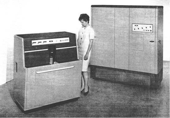 |
The name 'F.C.C.' was craftily chosen so that it stood for both 'Forty Column Computer' and 'Ferrite Core Computer'. The type number allotted to it was 558, which made it appear to belong in the family of calculators, whereas it actually was more nearly a full computer in the sense that we use the term.
Since it was designed to provide computing capability for forty column users, who tended to be smaller businesses and very cost-conscious, the machine was kept as simple as it could be, which actually meant that part of the job of programming an application was more complicated than it might have been.
The basic machine had one cabinet containing the processor and a second unit containing a card reader/punch. The processor had ferrite core storage for 128 words of program and 32 words of data storage; these could be increased to 256 words of program and 64 words of data. Another option was to add a second card reader/punch.
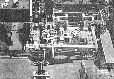
The cards were fed sideways, column 40 leading, through a photoelectric reading station, to a waiting position. The direction of travel then changed, and the cards were fed, with the top edge leading, through the punch station which was a conventional Powers type punching unit - the block comes down and all holes are punched simultaneously. Throughput was 540 cards per minute if no punching was done. If every card was punched that rate came down to 135 per minute.
There were two card receivers. They could either be filled sequentially, or the program could optionally direct selected cards to receiver 2.
Some Component parts
 |
The Data Store |
 |
The Arithmetic Unit |
 |
The Program Store |
Internal Arrangement
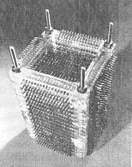
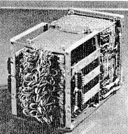
The data store was divided into two banks, imaginatively called A and B. Each word consisted of 10 data digits plus sign. B0, the first word of the B store, functioned as an input buffer. There were also eight words of output buffer, known as the C store, into which data to be punched was placed by the program.
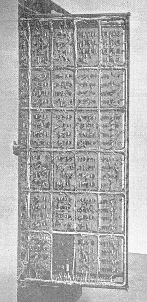
Data was held in decimal or sterling form, so again there was no inward conversion to binary and outward conversion from binary. But the program itself was held in binary form. The instruction format had five bits for the function code, five for an address in the A store, five for an address in the B store, and a single bit for the A/B suffix. So an Add instruction, for example, would add a number in the specified A store and a number in the specified B store, and place the result in either the A or the B address, depending on the setting of the A/B suffix bit.
There were only 20 instructions in the machine's repertoire, add, subtract (in both decimal and sterling versions), copy, halve, shift, modify, conditional and unconditional jumps, punch, send the card to stacker 2, and so on. There were no built-in multiply or divide instructions, but these functions were provided by subroutines which came with the machine.
The first 'subroutine' was in fact, a complete program. Its function was to convert the instructions of a user program, which the programmer punched in clear into the program cards, into binary. The binary form of each instruction was punched by this program into the same cards. There was a quirky feature to this punching: if the binary form of an instruction contained a row of successive 1s it was feared that this might weaken the card and so cause a misfeed. So the binary form was staggered diagonally across the columns, each 1 being represented by a hole, each 0 by the absence of a hole.
Once the program cards had been converted in this way they could be retained. Then in the normal procedure for a run the program pack would be read first, followed by the relevant data cards.
There was also a third form of input to a program in the form of a simple plug- board (I wonder where they got that idea from?). Its function was to define the layout of the data cards, explain the meanings of any control holes, and so on. The fields which would form factors for the program's calculations would normally lie at the right hand end of the card. So, as the card was read starting from column 40, characters would be read from successive columns into B0, the input buffer, until the plug-board signalled 'end of field'. At that point the first instruction of the program would be obeyed; it would always be a transfer from B0 to a location in the A store. This would be repeated for successive fields, each in turn being transferred into the A store, until the plug-board signalled 'end of sensing'. This would allow control to pass to the rest of the program.
The subroutine repertoire was reasonably comprehensive: multiplication and division, of course; various conversions - e.g. farthings to decimals, hours and minutes to hours and decimals and vice versa; quantities in dozens and singles, square root, graduated pension scheme, PAYE (normal cases only), weekly tax routine, monthly tax routine, and coin analysis - all functions which were likely to occur in conventional punched card application systems.
 |
Part of the Card Track |
It always seemed to me, as a layman, that the engineering of the F.C.C. was particularly neat. This shows the photoelectric reading station on the left, then the waiting station where the card sat while the program was executed, and then the punching station where the results were punched into the same card.
As a programmer, I enjoyed the little bit of work I did on the F.C.C., and I remember it with affection as a nice machine to operate. But it only had a short life. Despite efforts to keep its cost down to the minimum I suspect it was just too expensive for the average forty-column user.
This is the first part of an edited transcript of the presentation given at the Science Museum on the 19th of January 2012. The second part will appear in Resurrection 59.
Hamish Carmichael's professional career stretched from Powers Samas to the Fujitsu years without ever changing his employer. Since 1996 he has been a stalwart of the Society, having served as both Secretary and as Archivist. He can be contacted at hamishc@globalnet.co.uk.
When ICT merged with English Electric Computers in 1968, EEC's real-time department was hived off to another newly-synthesised company, Marconi Elliott Computer Systems. A group of EEC engineers, not wanting to relocate from Kidsgrove to Borehamwood, decided that, rather than be transferred to MECS they would start a new company: Information Computer Systems (ICS). ICS took over disused railway works in Crewe and proceeded to develop the Multum, a series of 16-bit real-time minicomputers that ranged from the basic Arithmetic Logic Processor/1 (ALP/1), comparable with a PDP-11/20, to the ALP/3, an 8MHz CPU with virtual memory and floating point hardware.
Designed as a multiprocessor complex, the Multum was more powerful than any contemporary PDP-11. In a maximal configuration it would have had four store modules of 128K bytes each, and eight processors, connected by a crossbar switch that allowed all four stores to be accessed simultaneously. Of the eight processors, up to four could be CPUs in any mix of ALP/1s, ALP/2s and ALP/3s (the ALP/2 was an ALP/3 without the floating point feature). The remaining processors could be any mix of Communications Processors, supporting asynchronous and synchronous line units; and Multiplexed I/O Processors, which were similar to IBM's Multiplexor Channels.
The Multum had some generic similarities, and some common roots, with the GEC 4080. An open question is how it related to another contemporary, the Marconi Locus 16, which also used the distinctive 'ALP' term for a CPU. Unlike the 4080, the Multum did not have a microcoded operating system kernel. That functionality was implemented in software, with the help of a very capable context switching instruction and a memory map providing each process with 16 variable length areas of up to 4K words. Each area could have its own access status, could be independently sized, and could be independently located in RAM, which was initially implemented as core storage with a 650ns cycle time.
The Multum was announced in early 1972, and by early 1973 the Computing Science Department at Glasgow University had acquired a pre-production model, with a view to conducting research in operating systems and compilers. So far as I know, this was the only ALP/3 configuration ever built. It had:
There was no crossbar switch, communications processor or multiplexed I/O processor. Instead, all the individual device controllers were fitted to the CPU's basic I/O processor, a DMA channel implemented in the CPU microcode.
The Computing Science Department contracted with ICS to develop a general purpose operating system to complement their real-time system. As a first step, a Multum Pascal compiler was half-bootstrapped (by Robert Cupples, John Cavouras and myself) from the ICL 1900 Series Pascal implementation by Jim Welsh and Colm Quinn. This made Multum Pascal the grandchild of Wirth's famous CDC 6400 implementation; it was probably the world's third Pascal compiler, and was almost certainly the first on a 16-bit minicomputer.
The operating system project got as far as testing a microkernel-based executive written in Symbolic Usercode Language, the Multum assembler; specifying major OS components; and prototyping a filing system written in Pascal.
Iain Smith's microkernel implementation was a piece of virtuoso programming. It had some syntax errors on its first assembly; it assembled, but quickly failed on a second attempt; and it ran perfectly at a third attempt, supporting a system of about a dozen concurrently executing processes. These consisted of a device driver process for each of the I/O devices, working in privileged state; and a set of processes working in user state, each of which copied data from one of the input devices to one of the output devices.
The Basic I/O Processor of the ALP/3 was a selector channel (in IBM terms). That is, it was dedicated to one DMA transfer at a time. To gain the efficiency offered by keeping I/O devices in simultaneous operation, the BIOP was timeshared by the microkernel, in a manner closely analogous to its timesharing of the CPU. This created a virtual BIOP for each peripheral. When the system test was running there were no discontinuities in the smooth operation of the various I/O devices, which performed close to their rated speeds. Virtualising the BIOP was made feasible by the fact that each controller had adequate buffering to keep its device going while it was not being serviced by the BIOP. We had quite a battle trying to persuade ICS to buffer the card reader properly, but eventually succeeded.
Running the system test gave us the pleasure of seeing the amber WAIT state lamp (on the ALP's front panel) light up for the first time. The microkernel Executive's IDLE task ran when no other process was in the READY state. It incremented a count of the number of times it had been dispatched and then put the CPU into the WAIT state - awaiting an interrupt - to free up store cycles for other processors in the complex; this being unlike the ICS executive, which busy-waited in these circumstances.
(Iain Smith eventually went on to DEC, where he worked on IAS, a timesharing system for the larger PDP-11s that was based on RSX-11D. The RSX/VMS family of operating systems have some interesting architectural and terminological resemblances to the Multum microkernel Executive.)
Then calamity struck. Testing the microkernel revealed a bug in the DMA channel, which shared a working register with the ALP's address-generation microcode, but failed to access it under mutual exclusion. ICS sent an engineer to make the necessary change, but struggled to implement it on the soldered wiring of the pre-production hardware.
Next a banking crisis blew up in the USA, and in August 1973 the financial backers of ICS abruptly withdrew their funding. Overnight the company was rendered insolvent and ceased trading.
Plus ça change ...
The microcode bug never was fixed, the computer rapidly deteriorated, and the project drew to a dispiriting close.
Register Structure
A Multum ALP/3 had the following working-register set:
A |
The primary 16-bit arithmetic register |
There was only one copy of these registers, so they were saved and restored as part of a context switch.
Address Generation And Addressing Modes
A 16-bit Multum instruction had room for, at most, eight bits of address constant; so almost all addresses were derived from the contents of registers. All of the working registers could be used in this way, but being few in number they had other uses that prevented their normal employment as bases. In mitigation, the Multum had the concept of memory-held registers. The P register was conventionally used as the base for the local variables of a procedure. The eight locations at [P]+0 through [P]+7 were that procedure's memory-held registers, and addressing modes were provided to allow them to be used as addressing bases. By initialising these words with suitable values, every procedure had at its disposal eight independent base pointers, the trade off being an additional store cycle to fetch the pointer value. (The eight locations at [P]+8 through [P]+F were also known as memory-held registers, but had much more limited functionality and could not be used as address bases.)
A Multum virtual address identified a 16-bit word, not a byte. An un-indexed byte handling order always accessed the most significant half of the word in store. However, if the addressing mode specified an index register, the content of the latter was taken to be a byte offset from the base address. This was achieved by shifting the index value right one place before adding it to the base address, to locate the word containing the byte. The bit that was shifted off at the right selected which of the two bytes in that word was to be the operand, byte 1 being the less significant half-word. Similarly, some orders had double-word operands, and here the address scaling worked in the opposite manner: the index was taken to be a double-word offset, and so was shifted left one place before being added to the base address. No shifting of the index value was done for word operands.
So the effect of an order with base address B and index i was always to access the ith item of the implied size, with the 0th item being located at the virtual address B.
Multum Software
Sadly, no source or object code for Multum software has survived, and very little ICS documentation.
Multum Roster
It is difficult to be sure how many Multum computers were built. There was an ALP/3 at GUCS, and there must have been at least an ALP/2 at ICS's Crewe base, because they completed an Executive with virtual memory support, which would have required extensive testing on a /2 or /3. There was also an ALP/1 there. I seem to remember that it had a drum store for efficient access to program development software. Another ALP/1 was owned by Monotype, in Redhill, presumably with a view to applications in typesetting. We believe that another was sold (but never delivered or paid for) to Brakspears of Henley, purveyors of fine ales.
Regrettably, I never photographed the ALP/3; but one of its designers, Dave Yardy, did. Visiting GUCS for a short conference of existing and potential customers, he seized the opportunity to view the configuration and take a picture. The occasion went with a bang - just as he entered the computer room, one of the large capacitors in the power supply exploded and shrapnel rattled around inside the cabinet. That fault was fixed very quickly!
Topsy
As delivered to Glasgow University, the ALP/3 was provided with a basic suite of paper-tape based software, consisting of: a text editor; a two-pass Usercode macro-assembler that generated relocatable object code; a two-pass relocator and linkage-editor, called Integrator; and an elementary program loader. Using these programs tried the patience: source code on paper tape had to be read into the assembler, respooled, and read again; assembly output tapes were fed twice through the Integrator in the same manner; and the integrated object program had to be respooled before being read into core by the loader. This was slow (always) and disaster prone (for the clumsy operator, like myself).
Our first priority was to exploit the disc drive to do away with paper tape handling as much as possible. To this end Iain Smith and I produced TOPSY, which was a minuscule subset of the facilities intended for the microkernel Executive. It allowed source code, object modules and loadable programs to be held in designated cylinders of the disc. A certain amount of manual intervention was still required, at the points where paper tapes were formerly respooled, but by redirecting I/O streams to the disc TOPSY hugely increased the convenience and celerity of program development. That made it practical for Pascal compiler development to be self-hosted on the Multum.
TOPSY's sole merit was that it worked. A user's guide survives, but I would be embarrassed to publish it!
Pascal Compiler and Puma
The Pascal compiler was half-bootstrapped from the #XPAC compiler for the 1900 Series. Robert Cupples used an ICL 1904A running GEORGE 3 at Strathclyde University to retarget the code generators, and then to make the retargeted compiler compile itself. The result was a very long roll of paper tape, output by the 1900 and carried to the Multum. It represented the compiler logic as a series of calls on Usercode macros. The latter implemented pseudo-instructions that were both more compact, and more convenient for the compiler, than plain Usercode. Nevertheless, it was a lot of text, and it took a long time to assemble on the Multum, even when TOPSY went into use. The bottleneck was the macro expansion process, which-we were dismayed to discover-was glacially slow, to the point that assembling the compiler took most of a working day. This was (just about) tolerable for once-a-week compiler updates from the 1904A, but unacceptable for Pascal programs that needed to be amended, compiled and tested several times a day on the Multum itself.
A partial solution was provided by PUMA, the Pascal Usercode Macro Assembler, coded up by Ian Christie. This was a load-and-go assembler written in Multum Pascal. It generated machine code directly, in a single pass, as fast as the compiler's output could be read. PUMA reduced the time taken to assemble and load a simple Pascal program, from many tedious minutes to a few fleeting seconds. We intended to similarly replace the Integrator with a disc-based linker, to be called LYNX, but that never got beyond the planning stage. Perhaps we should have trademarked the full range of feline product names!
The Microkernel Executive
The main design principle of the microkernel executive was that it should implement as much functionality as possible in virtual machines-that is, in processes-rather than in a monolithic supervisor. First-level interrupt handling, time slicing of the BIOP and the ALP, domain management, and inter- process communication (by message passing and segment sharing), were the sole work of the microkernel. Some interrupts, for example device interrupts signalling the end of a BIOP time slice, were fully handled within the microkernel. Others-for example those signalling the completion of an entire transfer request-were handed off to interested processes in the form of messages from the microkernel. A very low-overhead message passing mechanism was designed to make this practicable. Device management, program loading, segment management, swapping, scheduling, filing systems, and job management, were all intended to be the work of privileged and/or trusted processes written in Pascal.
In reality only the microkernel, a hand-crafted set of device driver processes, and a test workload, reached completion. The prototype filing system was later reused with floppy disc drives, in an embedded system logging data from a scientific experiment; so that was not a total loss.
The Dill-Russell Connection
ICS contracted a small software company, Dill-Russell Holdings, to supply it with FORTRAN and BASIC compilers. Dill-Russell engaged David Hendry, who had designed and implemented the Atlas FORTRAN V compiler. He planned to write the compilers in his low-level, machine-independent language SNIBBOL. Other members of the team included Dik Leatherdale, Tom Moran, Harry Martienson and Mary Lee, all formerly of London University's Atlas Computing Services. Dik Leatherdale was given the job of writing the runtime support routines for FORTRAN I/O, using the Monotype ALP/1 at Redhill, but was only six weeks into the job when ICS collapsed.
Applications Programs
To the best of my knowledge, only one genuine application program ever ran on the Multum, and that was rather abstruse. It was written by my GUCS colleague, the mathematician Jennifer Haselgrove, to discover a tiling of a 15×15 square by 45 Y-pentominoes. She wrote exquisitely crafted Usercode that exploited the Multum's complex addressing modes to represent the geometric data structures; and she provided ASCII-graphical output of the filled rectangles on the console VDU or line printer. Many years later her resulting publication was referenced by Donald Knuth, in a paper that contains the only mention of the Multum I have ever found in the broader literature.
Further Reading
A much more detailed description of the Multum instruction set, and a set of scanned documents, can be viewed at: www.findlayw.plus.com/Multum/Documents. Acknowledgements to John Cavouras, David Hendry and Dik Leatherdale.
Bill Findlay started making a living from computers the summer he left school in 1966, but spent most of the following 33 years at Glasgow University, teaching rather than doing. (He hopes the old adage does not apply!) In retirement he has been participating in the resurrection of the KDF9 and has written ee9, a KDF9 emulator. The author can be contacted at kdf9@findlayw.plus.com.
David Holdsworth's article in Resurrection 57 inspired me to take a month off from editing Resurrection and blow the dust off my long-dormant project - an emulator for the Ferranti Atlas 1. I have but one fragment of original code at present, but it's a rather good one, the run-time library for Atlas Basic Language - the Atlas assembler. There follows a cautionary tale.
I started work on my Atlas 1 emulator in 2004 and it has proceeded in fits and starts ever since. Of course I have an excuse. I generally have something more important, more immediate to do. But that's hardly a good excuse, is it? Nevertheless, David's article got me going again, after a “rest” of a couple of years.
The emulator comprises two parts: the emulator proper and a built-in compiler for Atlas Basic Language (ABL), linked together by a simulation of the Atlas virtual store. I could have made a copy of the ABL compiler which exists as a lineprinter listing at the University of Manchester but, since it's written in itself, that wouldn't have got me far. The downside of writing my own compiler is that I can never be completely sure that it's correct. I do, however have a lot of test programs which I've developed along the way and they seem to work.
But the acid test is when you come to try out an original piece of code. The National Archive for the History of Computing at Manchester, kindly provided me with a listing of the ABL run-time library which I re-typed some time ago - had I but read David's article beforehand, I might have saved myself a lot of grief. I had the output routines done and dusted three years ago, but when I came to look at the input routines, they seemed more complicated so I put them on one side.
Joining the Dots
 |
When I eventually came to look at them that they didn't compile cleanly. My first problem was with full stops where full stops shouldn't be. Look at the fourth line. There's a function code “2.14” which doesn't look right next to all the rest of the code and there's certainly nothing in the manual which covers such a thing. There are several others just like it. There was even a full stop on a line on its own. What could it mean? It had me stumped for a while.
Then I remembered. Atlas peripherals had differing character repertoires. This program would have been prepared on seven-hole paper tape in all probability. Add in the long-forgotten knowledge that when you tried to print a character that the printer didn't understand, it printed a dot. So is our “2.14” perhaps “2<any character><backspace><erase>14”? Just take out the dodgy dots and it works! Of course, there might be some dodgy dots lurking in places where real full stops are acceptable to the compiler, but I haven't found them yet. Things aren't always quite what they seem.
The Implied Zero
Now look again at our code fragment. There are three lines ending in “/” just in this fragment, more elsewhere. My compiler didn't like any of them. “A10” is by way of being a variable or a label. Quite what “A10/” means is unknown to me, unknown indeed to the manual. “A10/6” would mean “A10” in Routine 6 because helpfully, the ABL compiler has separate namespaces for each routine. But this is an assembler (which allows all sorts of constructs, no matter how unhygienic), so “A10/6” is our means of reaching into some other routine's scope. So we can take a guess that “A10/” might mean “A10/0” - the “A10” in Routine 0. So I changed the compiler and lo, it all makes sense! It was at this point that I realised what I was up against. The person who implemented the nice, straightforward output routines wasn't the same as the one who did the input - much more sophisticated - or obscure, if you prefer. Things are sometimes not what they seem.
More Equal than Others
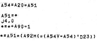 |
Now examine the fragment on the right. The first statement seems to read “A54=A20=A51” - a double compile-time assignment! Neither my compiler, nor the manual was happy about that. But emboldened by previous success, I set to and changed the compiler. Look at “*=*+A90=1”. What does that mean? “A90=1” and then “*=*+A90” perhaps? Tenuous? Mmm.
Now take a look at the last statement. No question there. That's not a double assignment. Complicated? Yes. Obscure? Certainly. But not a double assignment.
 |
But look more closely still at the first statement. Something isn't quite right there. That second “=” isn't exactly like the first is it? Look at the others and you'll see the same. Sometimes (let's be charitable) barrel printers weren't altogether accurate. Sometimes only the sharp edges of the characters came into contact with the ink ribbon. Suppose our second “=” was a “-”? Maybe, but it's not quite like the “-” in “A54V-A54” either, is it? Well after two days of struggling to understand the program I concluded that it was a “-”. Edit the program, remove the double assignment facility from the compiler and we're off to the next problem. Things are often not quite what they seem.
Law and Order
Finally look at that last statement again - “*=A51+(A92M(-(A54V-A54)'D23))”. Now I'm not going to attempt to explain all that now. It's probably the most sophisticated (deeply obscure) bit of ABL, I've ever seen. Lets concentrate on the middle bit “-(A54V-A54)'D23” pausing only to explain that the manual forswears any notion of operator precedence. Other than brackets, left to right working is the order of the day. We know that A54 is the difference between two other variables. Sometimes they have the same value, sometimes not. “A54V-A54” means A54 or -A54 which evaluates either to 0 or to a negative number. According to the manual we should apply the prefix minus (0 or a positive number), prime (') logically negates it (-1 or some other negative number) and D23 shifts it down 23 binary places (1 or 1). Which makes no sense at all.
Another few days studying the code and I concluded that what the program demanded was -1 or 0. After much tearing of hair and the use of pencil and paper, I concluded that we get that result if prefix operators are applied last. As before “A54V-A54” evaluates to 0 or to a negative number. Then we logically negate (-1 or a positive number), shift down 23 bits (1 or 0) and apply the prefix minus (-1 or 0) giving us the result we crave. Phew! Are things ever what they seem?
The conclusion I'd like to draw is to support David Holdsworth's notion of working with a partner with first-hand knowledge of the subject. If I'd had a partner with whom to share this grief, I would have saved myself a lot of effort. In the absence of whom, I've been using Bob Hopgood as a sounding board. He's been the very soul of patience. Thank you Bob.
When he's not pretending to be a programmer Dik Leatherdale pretends to edit this publication. So it's all his fault.
From Andrew Herbert
I was disappointed by the lack of support shown to an endeavour that I believe is very important and in which I have been personally very active.
First I should point out the focus is on computer science in schools, not programming and, even more importantly, on computer science as an academic discipline in contrast to the essentially vocational nature of the current ICT courses on offer.
If you read the Royal Society report you will see there is strong industry demand for computer scientists across many sectors, with the increasing dependence of businesses on a broad range of computing technologies and the widespread use of computer models and simulations. This demand is not being met by the universities, who have seen a decline in enrolments in recent years. The report further goes on to state that schoolchildren find the current vocational ICT course uninspiring and that many who might otherwise go on to become computer scientists are put off at any early stage.
There is no intention to “throw out ICT”″ and replace it with “programming”. Teaching ICT skills remains important, but this should be taught in the context of the subjects where the skills can be usefully applied rather than as a free-standing subject. By adding computing to the curriculum we hope to expose schoolchildren to the excitement and challenge of modern computer science and hopefully, motivate more of them to consider a computer science degree at university and computing as a career.
Obviously “programming” will be part of what is taught, but not exclusively: theoretical computer science, algorithms, human computer interaction, computer systems technologies and engineering, machine learning and perception, applications, ethical issues will all need to be introduced to set out the full scope of the subject.
I would hope CCS members would be supportive of what the Computing at School Group is trying to achieve and celebrate how much the field of computing has developed from the foundations of the systems we fondly remember and care for in our own endeavours as a society.
From Bryn Jones
I quite agree with you that teaching programming in schools is not required. I started computing in 1965 and ended up lecturing in an FE college in A-level computer science, and ICT to all types of pupils. I retired 20 years ago but I can see that programming is not what is required.
From David Steele
I think there is an important distinction to be made between programming concepts & theory and actual coding in terms of writing code in a particular language. I agree that we do not need a generation of programmers in a language that may itself be redundant by the time they look for jobs. However, there is a need to understand that most technology we use has a relatively complex interface still and as the interfaces are written almost exclusively by ″techies″ there is (and will remain for my foreseeable future) a need to have a some feel for how their minds work - hopefully in a well-trained systematic approach (often this is obviously not the case, but let′s be optimistic).
I agree that everyone needs to know how to use IT tools such as WP & spreadsheets (but would argue against teaching one specific product). The vast majority will never actually see code but I find my database knowledge invaluable in understanding how most filing systems/address books/contact management systems etc work.
From Nic Oatridge
I couldn′t disagree more strongly. In your editorial in Resurrection 57 you cast doubt on the value of learning programming in schools. Your point seemed to be that there was a limited market for games programmers.
The simple fact is that programming is fun. That should be enough reason to teach it, but importantly it also has utility. For every professional programmer there are hundreds of people coding in Excel, Access, VBA, PHP, HTML etc. For them to understand the underlying technology is not only interesting, it makes them more effective and promulgates professional standards. Code is everywhere. It is our profession′s gift to the world. You need no qualifications or budget to access it, and through it everything you see, hear, think, process or know can be de-constructed to a digital language that can be manipulated without limit.
For many of us working in commercial IT one of the biggest challenges is to ensure end-users, freed from the shackles of the IT department, write code that is intelligible for a successor, does not expose the company to the risk of outages, recognises issues of scalability and may even contribute to competitive advantage. This does not occur just in large enterprises, this is even true of the corner shop and one person business.
I believe that every child should learn at least the rudiments of code. It is depressing to see that other IT professionals value code so poorly.
| 20 Sep 2012 | Adapting and Innovating: The Development of IT Law |
Rachel Burnett |
| 18 Oct 2012 | Conserving the Past for the Future - Data Websites and Software |
Tim Gollins, David Holdsworth |
| 15 Nov 2012 | History of Machine Translation | John Hitchins |
| 13 Dec 2012 | Film Show | Kevin Murrell, Dan Hayton, Roger Johnson |
London meetings normally take place in the Fellows’ Library of the Science Museum, starting at 14:30. The entrance is in Exhibition Road, next to the exit from the tunnel from South Kensington Station, on the left as you come up the steps. For queries about London meetings please contact Roger Johnson at r.johnson@bcs.org.uk, or by post to Roger at Birkbeck College, Malet Street, London WC1E 7HX.
| 18 Sep 2012 | Centring the Computer in the Business of Banking: Barclays 1954-1974 |
Ian Martin & David Parsons |
| 16 Oct 2012 | Manchester′s Telecoms Firsts | Nigel Linge |
| 20 Nov 2012 | The Design of Atlas | |
| Jan 15 2013 | Andrew Booth | Roger Johnson |
North West Group meetings take place in the Conference Centre at MOSI - the Museum of Science and Industry in Manchester - usually starting at 17:30; tea is served from 17:00. For queries about Manchester meetings please contact Gordon Adshead at gordon@adshead.com.
Details are subject to change. Members wishing to attend any meeting are advised to check the events page on the Society website at www.computerconservationsociety.org/lecture.htm. Details are also published in the events calendar at www.bcs.org and in the events diary columns of Computing and Computer Weekly.
MOSI : Demonstrations of the replica Small-Scale Experimental Machine at the Museum of Science and Industry in Manchester are run each Tuesday between 12:00 and 14:00. Admission is free. See www.mosi.org.uk for more details
Bletchley Park : daily. Exhibition of wartime code-breaking equipment and procedures, including the replica Bombe, plus tours of the wartime buildings. Go to www.bletchleypark.org.uk to check details of times, admission charges and special events.
The National Museum of Computing : Thursday and Saturdays from 13:00. Situated within Bletchley Park, the Museum covers the development of computing from the wartime Tunny machine and replica Colossus computer to the present day and from ICL mainframes to hand-held computers. Note that there is a separate admission charge to TNMoC which is either standalone or can be combined with the charge for Bletchley Park. See www.tnmoc.org for more details.
Science Museum :. Pegasus “in steam” days have been suspended for the time being. Please refer to the society website for updates. Admission is free. See www.sciencemuseum.org.uk for more details.
CCS Web Site InformationThe Society has its own Web site, which is located at ccs.bcs.org. It contains news items, details of forthcoming events, and also electronic copies of all past issues of Resurrection, in both HTML and PDF formats, which can be downloaded for printing. We also have an FTP site at ftp.cs.man.ac.uk/pub/CCS-Archive, where there is other material for downloading including simulators for historic machines. Please note that the latter URL is case-sensitive. |
Contact detailsReaders wishing to contact the Editor may do so by email to |
| Chair Rachel Burnett FBCS | rb@burnett.uk.net |
| Secretary Kevin Murrell MBCS | kevin.murrell@tnmoc.org |
| Treasurer Dan Hayton MBCS | daniel@newcomen.demon.co.uk |
| Chairman, North West Group Tom Hinchliffe | tah25@btinternet.com |
| Secretary, North West Group Gordon Adshead MBCS | gordon@adshead.com |
| Editor, Resurrection Dik Leatherdale MBCS | dik@leatherdale.net |
| Web Site Editor Alan Thomson MBCS | alan.thomson@bcs.org |
| Meetings Secretary Dr Roger Johnson FBCS | r.johnson@bcs.org.uk |
| Digital Archivist Prof. Simon Lavington FBCS FIEE CEng | lavis@essex.ac.uk |
| Archivist Dr David Hartley FBCS CEng | david.hartley@clare.cam.ac.uk |
Museum Representatives | |
| Science Museum Dr Tilly Blyth | tilly.blyth@nmsi.ac.uk |
| MOSI Catherine Rushmore | c.rushmore@mosi.org.uk |
| Bletchley Park Trust Kelsey Griffin | kgriffin@bletchleypark.org.uk |
| TNMoC Andy Clark CEng FIEE FBCS | andy.clark@tnmoc.org |
Project Leaders | |
| SSEM Chris Burton CEng FIEE FBCS | cpb@envex.demon.co.uk |
| Bombe John Harper Hon FBCS CEng MIEE | bombe@jharper.demon.co.uk |
| Elliott Terry Froggatt CEng MBCS | ccs@tjf.org.uk |
| Ferranti Pegasus Len Hewitt MBCS | leonard.hewitt@ntlworld.com |
| Software Conservation Dr Dave Holdsworth CEng Hon FBCS | ecldh@leeds.ac.uk |
| Elliott 401 & ICT 1301 Rod Brown | sayhi-torod@shedlandz.co.uk |
| Harwell Dekatron Computer Johan Iversen | jo891979@talktalk.net |
| Computer Heritage Prof. Simon Lavington FBCS FIEE CEng | lavis@essex.ac.uk |
| DEC Kevin Murrell MBCS | kevin.murrell@tnmoc.org |
| Differential Analyser Dr Charles Lindsey FBCS | chl@clerew.man.ac.uk |
| ICL 2966 Delwyn Holroyd | delwyn@dsl.pipex.com |
| Analytical Engine Dr Doron Swade MBE FBCS | doron.swade@blueyonder.co.uk |
| EDSAC Dr Andrew Herbert OBE FREng FBCS | andrew@herbertfamily.org.uk |
| Tony Sale Award Peta Walmisley | peta@pwcepis.demon.co.uk |
Others | |
| Prof. Martin Campbell-Kelly FBCS | m.campbell-kelly@warwick.ac.uk |
| Peter Holland MBCS | p.holland@talktalk.net |
| Pete Chilvers | pete@pchilvers.plus.com |
Readers who have general queries to put to the Society should address them to the Secretary: contact details are given elsewhere. Members who move house should notify Kevin Murrell of their new address to ensure that they continue to receive copies of Resurrection. Those who are also members of the BCS, however need only notify their change of address to the BCS, separate notification to the CCS being unnecessary.
The Computer Conservation Society (CCS) is a co-operative venture between the British Computer Society, the Science Museum of London and the Museum of Science and Industry (MOSI) in Manchester.
The CCS was constituted in September 1989 as a Specialist Group of the British Computer Society (BCS). It thus is covered by the Royal Charter and charitable status of the BCS.
The aims of the CCS are to
Membership is open to anyone interested in computer conservation and the history of computing.
The CCS is funded and supported by voluntary subscriptions from members, a grant from the BCS, fees from corporate membership, donations, and by the free use of the facilities of both museums. Some charges may be made for publications and attendance at seminars and conferences.
There are a number of active Projects on specific computer restorations and early computer technologies and software. Younger people are especially encouraged to take part in order to achieve skills transfer.
|
Resurrection is the bulletin of the
Computer Conservation Society. Editor - Dik Leatherdale Printed by - BCS, The Chartered Institute for IT © Copyright Computer Conservation Society |