| Resurrection Home | Previous issue | Next issue | View Original Cover | PDF Version |
Computer
RESURRECTION
The Journal of the Computer Conservation Society
ISSN 0958-7403
|
Number 99 |
Autumn 2022 |
Contents
| Society Activity | |
| News Round-Up | |
| Professor Tilly Blyth | Rachel Burnett & Dik Leatherdale |
| ICT 1301 “Flossie” 60th at TNMoC in 2022 | Stuart Fyfe |
| Using One Historical Computer to Emulate Another | Lee Wittenberg |
| Two Manchester Computer Milestones | Simon Lavington |
| 50 Years Ago .... From the Pages of Computer Weekly | Brian Aldous |
| Forthcoming Events | |
| Committee of the Society | |
| Aims and Objectives |
Society Activity
|
EDSAC — Andrew Herbert In recent weeks we appear to have got past our problems with the Main Control subsystem (order fetch and decode) and the Coincidence subsystem (store access timing) having devoted significant effort to improving the robustness of the circuits to valves going “soft” and lowering signal levels. The final piece of the puzzle was to boost the D0 (digit zero) signal from the clock subsystem with a local amplifier in the middle row of racks where Main Control and Coincidence are located — as this signal generally marks the start of processing of a new word either as instruction or data it plays a critical role throughout the machine. We are now running programs to test the correctness of calculations performed by the arithmetic subsystem (which the pioneers called “the computer”). We have observed many of the arithmetical orders being executed in test programs, but have not yet started to check the answers... There have also been improvements in the memory tank addressing system which have helped suppress random corruption of data in the main store. In a parallel development we have installed the first of a number of small microprocessor based monitoring systems to monitor the principal clock and digit pulse signals. The intention over time is to develop a series of monitors and watchdogs to aid in fault diagnosis. (Test programs are of limited diagnostic use in EDSAC as most of the machine has to be working for a test program to load and execute — but they will have a role to play in checking the long term stability of the main store and the correctness of arithmetic and input/output operations.) |
|
Turing-Welchman Bombe — John Harper
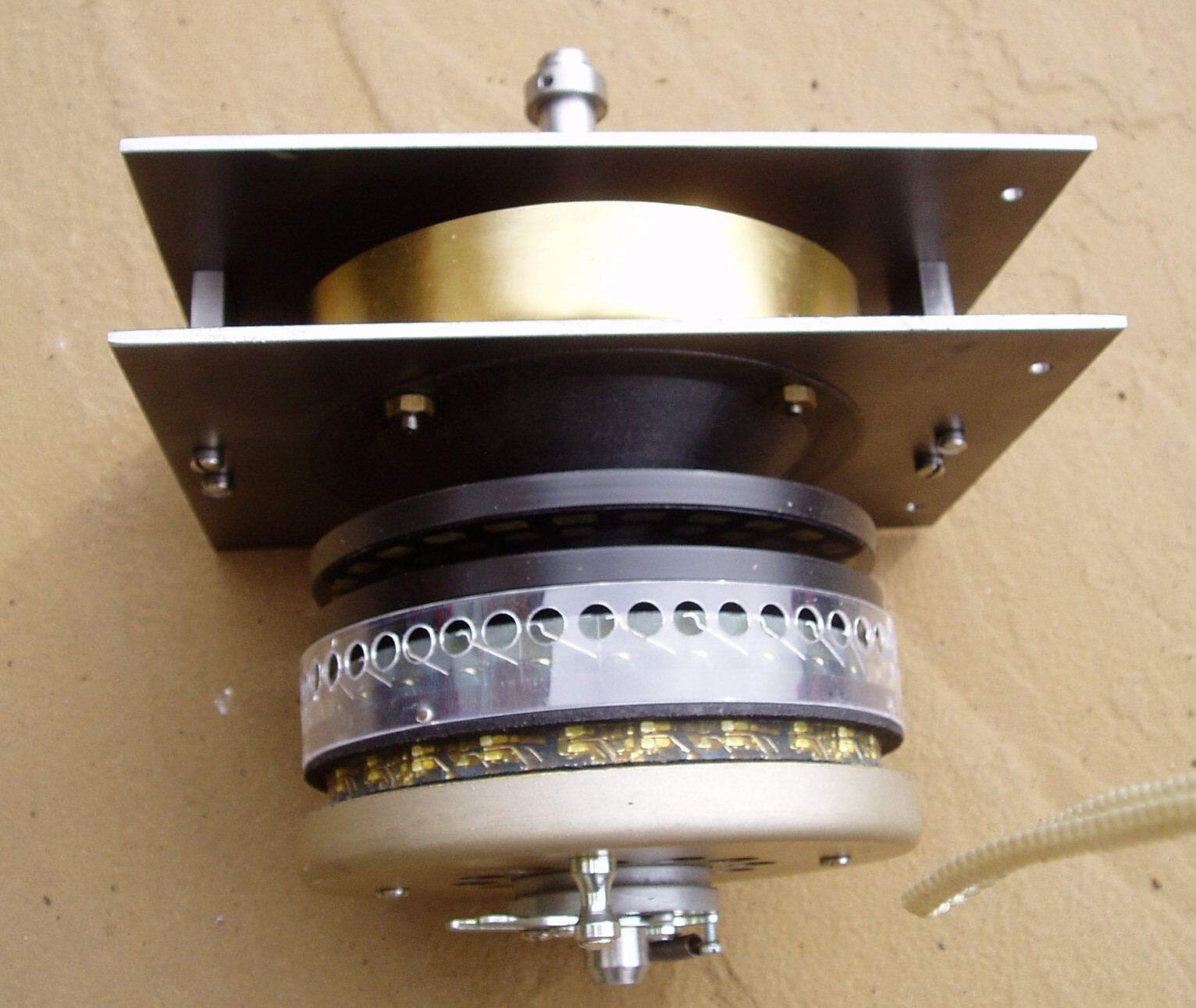
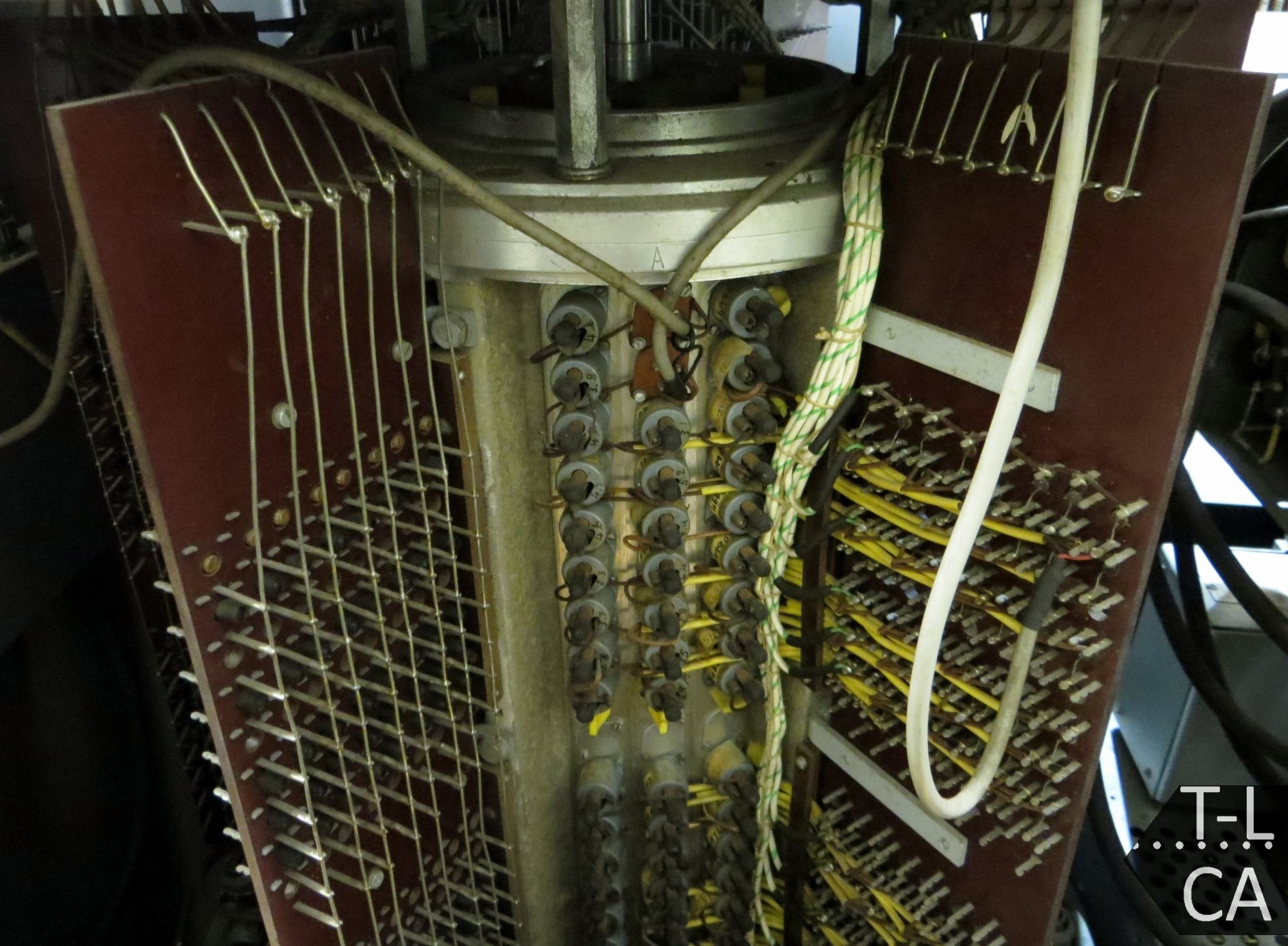
The second demonstrator is one of the 36 ‘Very Fast Drum‘ mechanisms as fitted to 60 or so High Speed Keen machines. On the machines that broke the German Navy submarine Enigma, four drums were required to match the four wheels in the German navy enigma. To find a good ‘stop‘ there were 26 more tests to be made at each cycle. To complete a run the 36 fast drums had to revolve 26 times faster than the fast drums on a three-wheel machine. Because of this much higher speed, the heat produced by the drum contacts on the commutator had to be cooled. To achieve this a fan was fitted to all 36 Very fast mechanisms. The flow of air is directed into a fan chamber by a cone. |
|
ICT/ICL 1900 — Delwyn Holroyd, David Wilcox, Brian Spoor, Bill Gallagher Brian has been helping a journalist to prepare an article about the George 3 executive emulator. This will be published in edition #295 of Linux Format, due out on 25 h October. David has been working on getting the 7210 IPB working and appears to be making quite a lot of forward progress, some of which is impacting on the PF56/1900 DDE interface, hopefully resulting in an increase in reliability. Bill and Brian have been doing some more testing on the 7930 scanner, picking up from where it was left a few years ago. It will be needed for the PF56/7903 implementation and is easier to fault find with the direct 1900 connection, without the 7903 DCP in the way. The code is working reasonably well, but clearing the last few problems is a struggle. The ICL hardware test programs are pointing to faults, but our own PERI level test programs are working, possibly because of compensating errors. MAXIMOP built for teletypes and scanner appears to be happy, but when built for working through a suitably configured Communications Manager is not so happy. |
|
Harwell Decatron — Delwyn Holroyd
A capacitor in the 370V supply circuit went short circuit, resulting in loss of regulation. The fault also took out a resistor supplying grid current. We discovered the failed capacitor had been operating above its maximum voltage, so it is surprising it lasted so long! This was closely followed by a short circuit capacitor in the Translator unit, which is responsible for converting between the five-hole code used on the paper tapes and in the relay circuits, and the pulse sequences found in the Arithmetic unit and stores. Surprisingly, six capacitors were fitted but only five were in use (one for each paper tape channel). We tested the unused component and it appeared to be sound, so the fix was simply to move a wire over! Pictures of the machine from 1951 show the six capacitors in place, so they are an original feature — we can only speculate! Next came a relay fault, the symptom of which was two digits of an order being marked out into the same relay set, causing an invalid code and the machine to stop. Even though it was happening every few minutes, this was still a very challenging problem to diagnose. The digit relay sets were suspected, and by making various swaps this was confirmed. With this clue and further examination of the drawings, it became clear exactly where the fault must lie. On inspection we found pips had grown on a set of changeover contacts, resulting in all three contacts being intermittently shorted together. We had also noticed that the relay power supply voltage was rather low — around 42V instead of the nominal 50V. This is due to ageing of the selenium rectifiers in the supply. Although it isn‘t causing a problem yet, we decided to take these out of circuit before one of them fails, and replace with a solid state rectifier bridge, as had already been done at Wolverhampton in the arithmetic unit power supply. The superior efficiency of the solid state rectifier meant the output voltage was now much too high. We could partially compensate for this by altering taps on the transformer, but still needed to drop another five or six volts. This is done with a set of eight high power diodes mounted on a heatsink. As usual the changes can easily be backed out. Some of the wiring also needed replacing due to the insulation cracking. |
News Round-Up
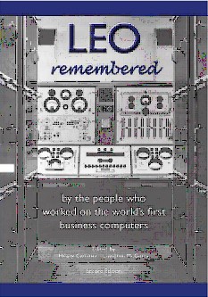
Our ever-active friends at the LEO Society have just published a new and much-expanded edition of LEO Remembered, an anthology with over 80 first-hand accounts of working with LEO, the world‘s first business computer. Georgina Ferry, author of the seminal tome A Computer Called LEO, wrote of the first edition “The human side of LEO‘s unique contribution to the history of computing comes to life in this captivating collection of reminiscences, testifying to a sense of collective endeavour among the LEO community”. 101010101 No edition of Resurrection would be complete without news of Herbert Bruderer‘s latest publications. On this occasion he has carefully assessed the influence of the various very early computers. Go to ccsoc.org/bru8.htm to read his conclusions. ccsoc.org/bru9.htm considers the claim that Ada Lovelace was the first programmer. 101010101 Dan Hayton reports that a copy of the very first COBOL manual presented by Grace Hopper to John Locke RN has passed through various hands including our own and has now found a proper home at TNMoC. 101010101 Apologies to members who were hoping to attend our September lecture which was cancelled. It is hoped that it will take place early in 2023. 101010101 Roger Johnson reports that the papers of the late Peter Landin have been catalogued at Oxford‘s Bodlean Library and are available for research. Landin was active in the development of the Algol language and latterly was professor of computer science at Queen Mary University. |
Professor Tilly BlythRachel Burnett & Dik Leatherdale
It is with much pride and pleasure that we can report that our good friend Tilly Blyth has been appointed Professor of Museum Studies at the University of Leicester. Following an early career in IT, Tilly joined the Science Museum in London in 2003 applying those early interests to the development of computer history at the Museum. Rising to Head of Collections and Principal Curator by 2016, she served on the Society committee as Science Museum Representative from 2005 to 2014. Representatives of the Science Museum and the Museum of Science and Industry, part of the co-operative venture with CCS, sit on the CCS Management Committee both museums being within the Science Museum Group. Tilly was a developer of two of the Museum’s galleries in which computers are particularly featured and was a key organiser of the two major computer history conferences with which the Society was heavily involved. During a secondment to the British Library, she organised recorded interviews with various computing pioneers the results of which can be found at www.bl.uk/voices-of-science/interviewees/. During Tilly‘s time as representative, the relationship between the Museums and the Society became more formal. We owe Tilly our gratitude for her contributions through the years, and for her help in clarifying the terms of this relationship. From time to time the inherent potential tension between conservators and expert engineers had to be addressed, particularly in the context of the respective perspectives on the role of restoration and reconstruction projects; and as the area of computing at the Science Museum was redeveloped, becoming part of the Information Age Gallery. We hope we shall maintain our friendship with her in her new post and that we shall perhaps hear from her again ‘ere long. |
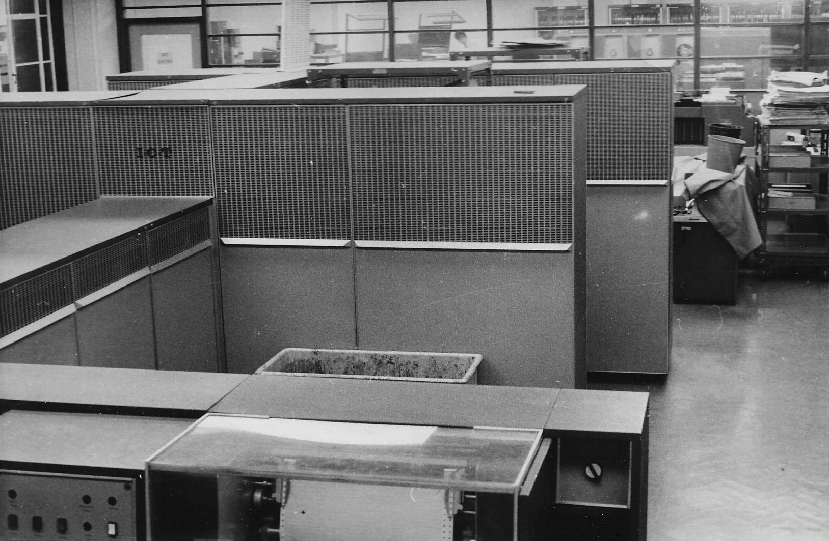
ICT 1301 “Flossie” 60th at TNMoC in 2022Stuart FyfeAmong the world‘s oldest working original transistorised large computers when donated to The National Museum of Computing at Bletchley Park, ICT 1301 serial 6, “Flossie”, dates from 1962. This th anniversary year, 2022, has seen the arrival of a 3D simulator for PCs etc, with proper 1301 programs and controls, just like the real thing. “Flossie” is currently in off-site storage pending installation as a working centrepiece exhibit.
Physically huge, but technically easy to understand due to a simple architecture, it ran one program at a time, then waited for the operator to feed the next as punched cards. No operating system, no screen or keyboard, it‘s all “twiddle the knobs and watch the flashing lights”. Simple hardware and software makes this a great teaching machine. History & Adventures In 1962, serial number 6 was still a prototype intended for internal software development when London University told the Government there‘d be no student intake that year if they didn‘t have the machine they‘d ordered. So, the then President of the Board Of Trade got ICT to assign the first machine. This is visible in the extensive technical documentation of modification history. We believe installation was first at Bush House as a punch card and printer system, with half inch magnetic tape being added when moved to Senate House. The list price would be £68,000 for the basic machine in 1962 (£250,000 when fully installed with ancillaries). By the time production ended in 1966, ICT had sold around 200 systems. So this is both the first, and now the last of its type.
As a general purpose commercial system it had one of the first high speed printers (600 lines per minute, 120 characters wide), producing G.C.E. certificates and allocating student accommodation until the university upgraded to a new ICL 1904A in 1971. The university was happy to pass the 1301 on to a group of engineering students, for educational use, at a scrap price of £200.
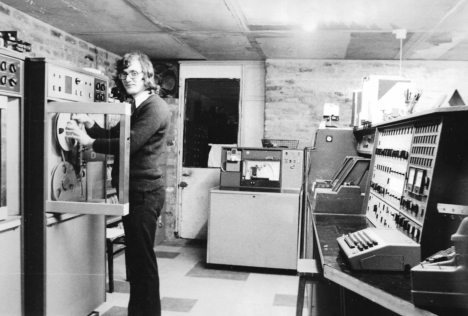
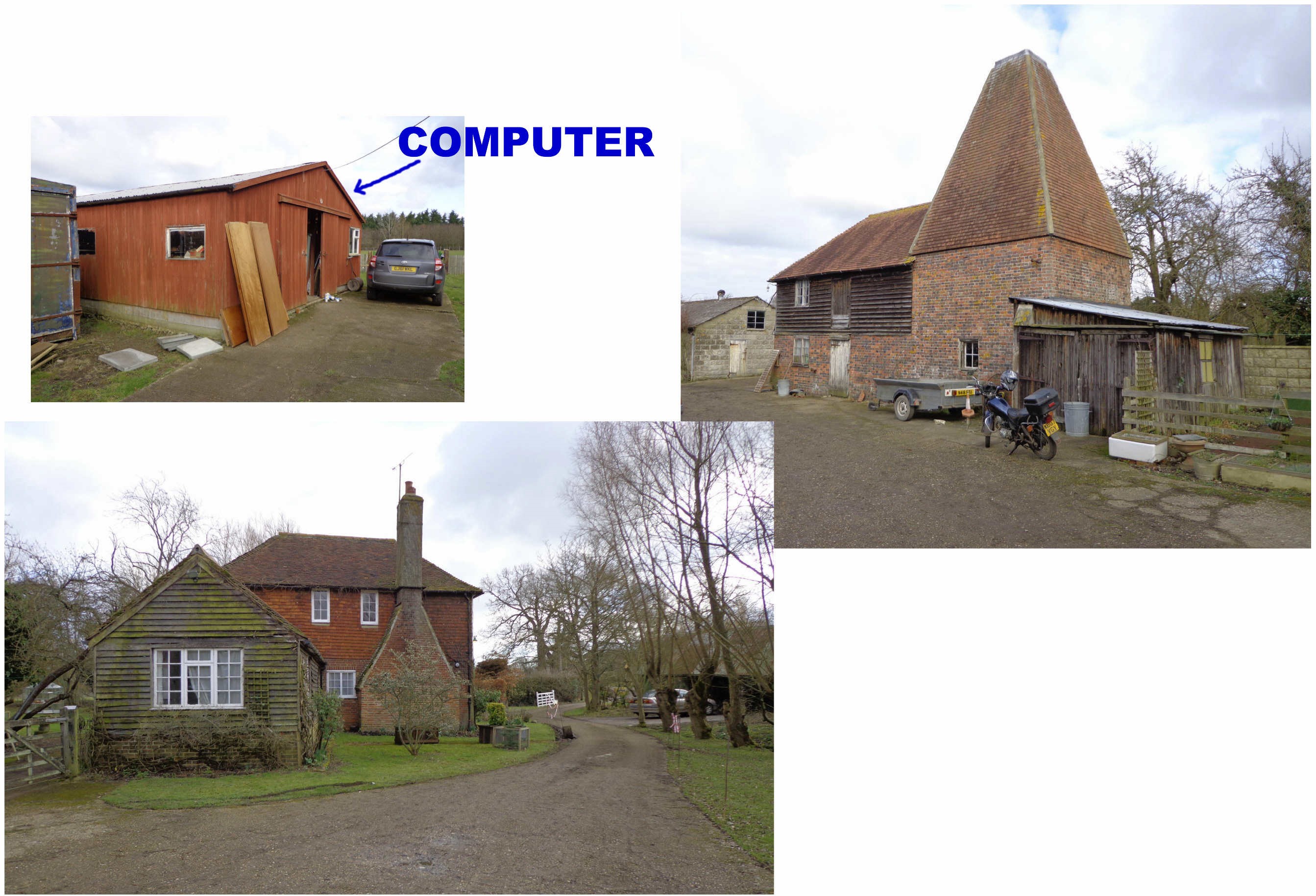
These students at Kingston Polytechnic (now University) called themselves “Galdor Computing” and created a purpose built workshop at their flat in Surbiton. The machine was named “Flossie”. With low overheads, they sold bureau services to all comers and maintained the national membership subscription records for the likes of London Village; Amnesty International; Friends Of The Earth; Town & Country Planning Association, and many others; printing mail-out labels and lists. School visits were popular; demonstrations, and the chance to experiment with hardware & software techniques “hands-on”. Plenty of spare parts arrived when more sites upgraded. Eventually, Galdor needed space for a growing collection of the ICL 1900 range, and in 1977, “Flossie” was passed on to Roger Holmes at Buss Farm in Kent.
Hardware
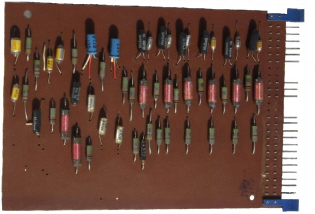
In 1962, the 1301 was made with pairs of discrete PNP germanium transistors (as a binary flip-flop) and groups of diodes (as logic gates) on single sided printed circuit boards five by seven inches. Some other components (coils etc) are there to sustain the logic output level long enough to be clocked (gated) into a following card. Some 5000 cards in dozens of types are interconnected with wire wrapped joints for reliability. “Flossie” has been moved successfully several times. 48 bits form a “word”, treated as Binary Coded Decimal (BCD). That‘s 12 decimal digits, each being four bits and normally holding a value 0 to 9. These digit groups are easy for a human to read on the console display lights. When performing arithmetic instructions, the “mill” juggles the carry between digits to maintain a BCD result. This idea is extended to work in sterling currency — automatically carrying (0 to 11) pence to shillings, shillings to pounds — allowing this commercially oriented machine to perform a task in hardware, which otherwise would involve frequent calls to software subroutines. Any “add” instruction still takes 21 microseconds. The printer includes halfpenny and farthing characters as well as “10” and “11”. A switch was added by Galdor so that, when selected, the sterling functions would work in straight 48 bit binary. Four-bit digits can still hold values up to 15 when not performing arithmetic, which is useful in other ways, like the end-of-block marker on magnetic tape. BCD is a compromise between fast 48 bit parallel (would need 48 data paths & lots more floor space) verses serial 48 bits chasing along a single data path (cheaper but too slow to be useful). Only 12 clock pulses are needed to move a BCD register in a serial fashion.
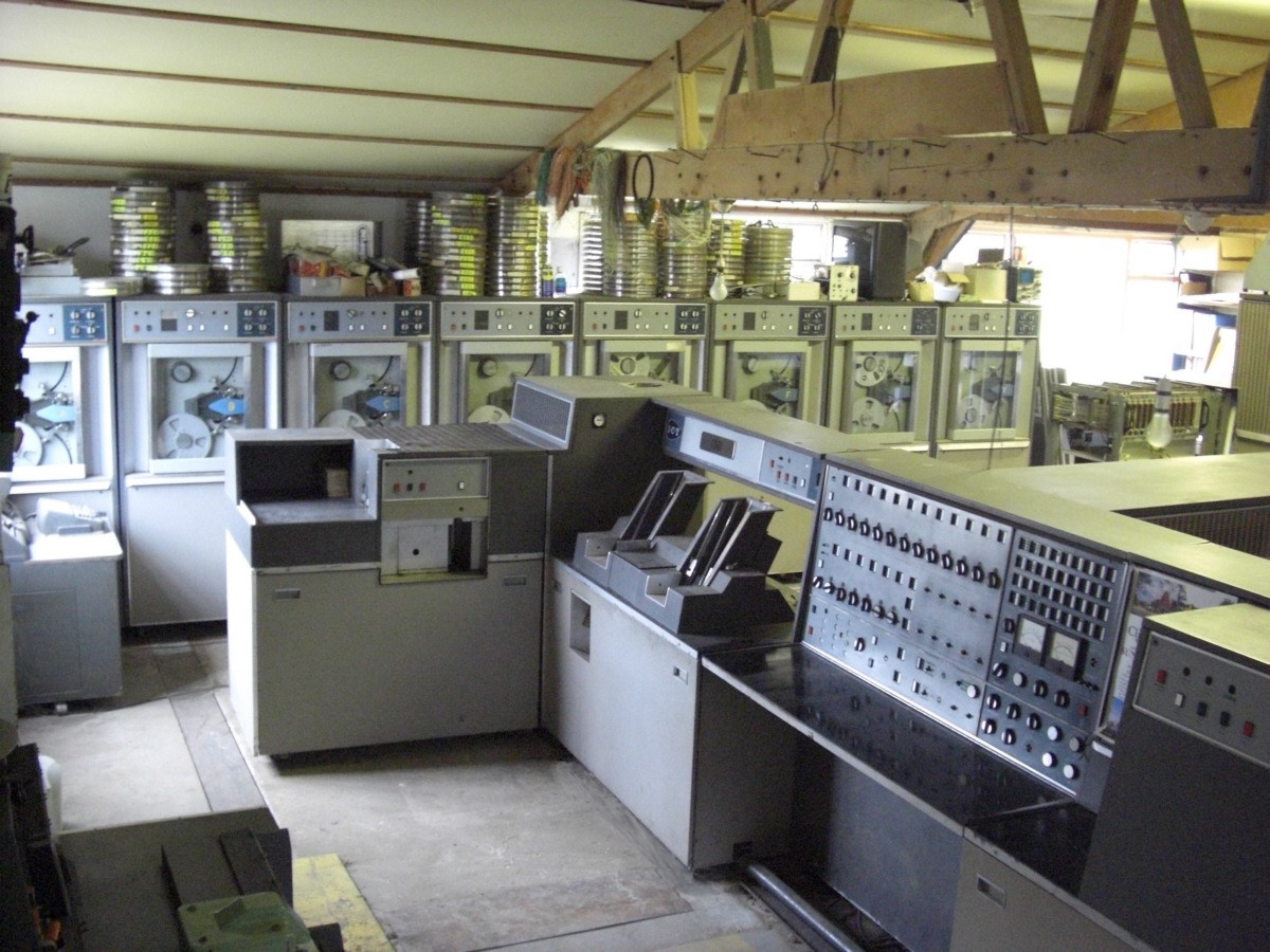
Memory is: Firstly, magnetic core store as 2000 words of 50 bits (48 + two parity), or 12 Kilobytes in modern terms. At a clock rate of one megahertz, it‘s called Immediate Access Store (IAS), transferring all 48 bits in parallel, in a couple of microseconds. Then, there‘s the magnetic drum store where a rotating vertical cylinder with magnetic oxide coating is surrounded by stationary read/write heads, 72Kbytes plus spares, transferring up to 200 words at a time to/from IAS with parity added and checked automatically. The 1MHz processor clock is phase-locked to a timing track on whichever is the current drum, for synchronising drum transfers. The original 1962 phase circuit was somewhat unstable, only working for a narrow range of drum speeds. Galdor substituted a 1970s device (which is the only integrated circuit chip on board), giving a crisper waveform, and working whatever the drum might do; impressively demonstrated by turning off the drum motor to see how long the processor runs. Magnetic tape is for the permanent storage of data files and programs, as well as making a scratchpad for larger intermediate results. ICT options were: 10-track ½” tapes (as in “Flossie”) giving up to 6Mbytes per reel; or 16-track 1” tapes; or slow ¼”, all with schemes for hardware parity checks and automatic error correction. Of the 10 tracks, four tracks are data (one digit per frame), while the others provide redundancy & recovery. “Flossie” came with four tape transports, more were added from other “scrap” machines. It is capable of accommodating eight and importantly, allows both reading and writing to occur concurrently on two different tape drives using Direct Memory Access (DMA) to transfer data to/from IAS, all while the user‘s program is busy preparing the next data block! The tape system is a reasonably autonomous peripheral. The control logic occupies most of the rear cabinets. Program routines check for error flags, and manage continuation reels if needed, communicating with the operator by halt codes on the lights. An ICL 1900 series standard interface (and 9 track 1900 tape drive) was added on another DMA channel to help other 1300 sites convert their data tapes when upgrading. Other devices are unbuffered, which means, for example, that the main program has to loop and wait for the printer barrel to rotate to the next letter you want to print. All this supervision is concealed in standard modular program subroutines, which might be better thought of as device-driver modules. The clock speed of one megahertz is pushing it for germanium transistors of the day. Waveform rise-times equate to say, 20MHz. Program instruction times are measured in microseconds, while anything mechanical like the printer is working on a millisecond scale — a thousand times slower, so a program can keep many gadgets running simultaneously if it wants to. Core store (IAS) comes in assemblies of 400 words. While “Flossie” has the maximum five of these “barn doors” (=2000 words), the 1300 series existed in several versions with less storage and slower peripherals. It‘s remarkable what can be done in, say, 800 words when there are no graphics or media to manipulate, just data records comprising a few dozen words. The drum holds overlays of chunks of program, and more data etc. Programs can be small but achieve a lot because there‘s no operating system. The cunning programmer has complete control, writing straightforward machine code, able to modify or create, its own instructions, which are, of course, just numbers. Most machine code instructions are six digits (a function code with an address), so two instructions can be held in a 12 digit word. Double length (12 digit) instructions are needed when two addresses are quoted e.g. IAS/drum transfers. The most unfamiliar concept in the 1300s would be the loop of three circulating instruction Control Registers (CR) which avoids the need for a dedicated program pointer. Each time they circulate, an unconditional jump address is incremented unless superseded by programmed test & jump. This trick is also the route to calling subroutines while preserving return jumps to the calling program. The instruction codes have gaps where new functions could be made by adding diode logic gates to do something interesting. In this way, Galdor added a useful instruction (28) to temporarily index or modify a following instruction by adding the content of an IAS location.
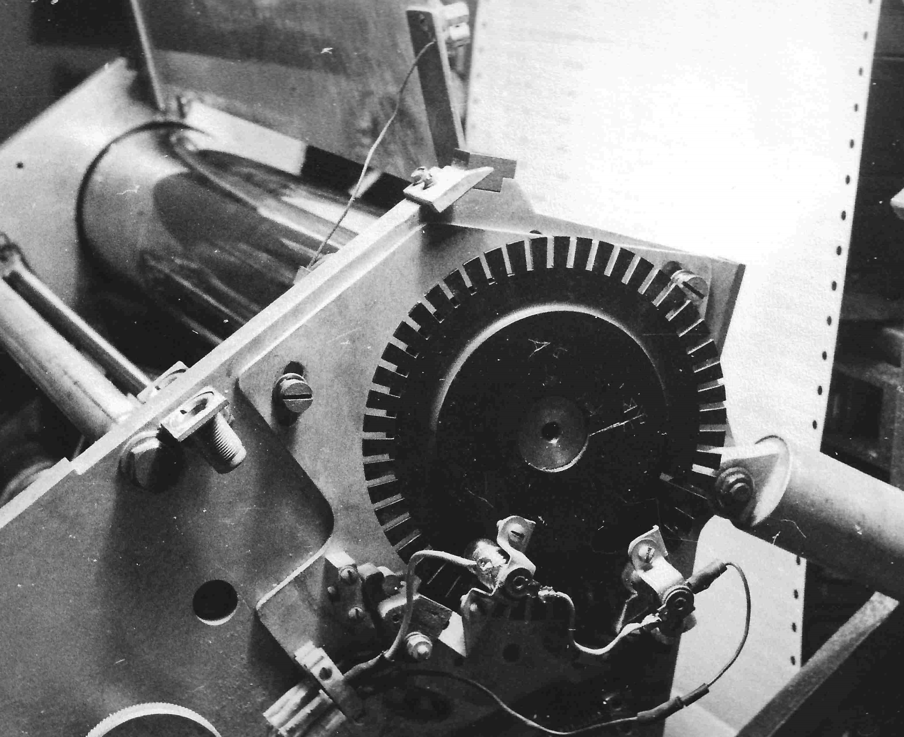
Lights shine through a slotted index wheel in the printer, so a counter can keep track of which character is under the print hammers as the barrel rotates. The processor program then selects which print hammers to trigger. Similar optical methods inform the progress of a punched card through the reader track. A small loudspeaker emits a click when any test-and-jump instruction succeeds. This is useful to keep track of the progress of a program, and inevitably gave rise to some recreational music. A few context switching 1302s were built with expanded core store that could run four programs “at the same time”, one of which was an “executive” (residing on drum), and communicating with the operator by typewriter. It included 1900 series standard interfaces. Please get in touch if you have information or experience of the 1302, which clearly is the forerunner of much that we recognise now. Software
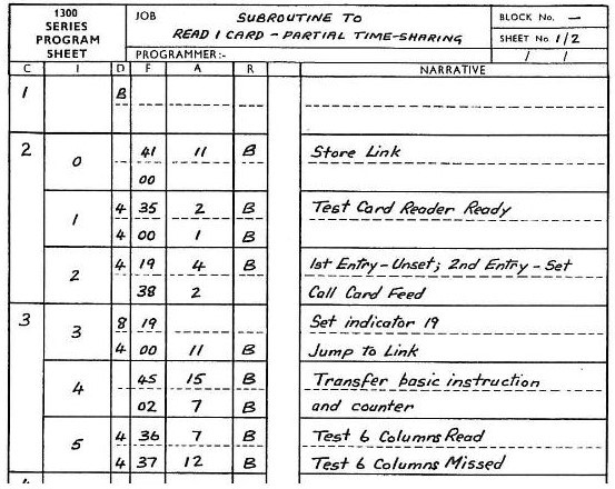
Running a 1301 operating system is not really possible because there are no interrupts or any memory protection or even relative instructions for that matter, everything being absolute once loaded into memory (IAS). Programming starts with a flow chart of elementary operations (like “add VAT to goods”) and decisions (like “was that too much?”). Machine code instructions are substituted for each element (like “620110” where: 62 means add, and 110 might be where VAT was stored), then punched as a pattern of holes on cards for the computer to read into IAS. That‘s great when the programmer has control of the entire machine and chooses exactly where in IAS the program and data will reside. Demonstrations and engineers‘ test programs are written like that. Individual instruction codes can also be entered at the control console, and you can watch the data moving about on the lights (slowed clock speed for demo & fault tracing etc). More general programming needs to incorporate standard ready-made library routines, requiring a different technique as follows — Each program’s size is different, so routines like “read a punched card” are written in relative (relocatable) format and get incorporated in the user‘s program, potentially residing anywhere in IAS. A pack of punched cards containing the user‘s program plus any routines, is read by a link-loader program to combine them together. The link-loader, called Initial Orders (IOs) turns relative into absolute addressing ready for execution. A console button calls IOs on reserved drum tracks. It only needs to know the size of each module. Significantly, in some form, almost every computer does this. Building on this technique, assembler languages exist for the 1301 (MPL, TAS) with function calls for printing etc, and introduce named variables, mnemonics, macros, comments,... from which, high level languages like COBOL can be made. Data records on magnetic tape are necessarily maintained in a linear sequential order (e.g. alphabetic), so any changes required are also presented (sorted) in a similar sequence, and combined to make fresh (updated) sets of tapes. The largest commercial applications might need dozens of tapes to hold a file. Sorting is therefore a big issue. Galdor added a pre-pass to the ICT sorting program, using the drum store to sort files into ordered chunks before involving slow tape-based merge-sorts. This was done by bubble sorting an index in IAS and retrieving the records from drum wherever placed, treating the drum as a random access device. Small files no longer need the tape sort at all. Initial Orders can be modified, with care. A useful improvement is running sequentially a number of programs by reading single punched cards, then finding the required program image in a library tape (kept on-line on deck 7) .... instead of having the operator feed lots of punched cards containing each complete program, each time. It‘s a mystery that ICT did not supply such things as it was not that difficult. Computer Museum Several ICT1301 emulator programs have been developed. The most impressive and most recent is a fully 3D simulator by Martin Gillow unveiled at the Museum 30th April 2022.
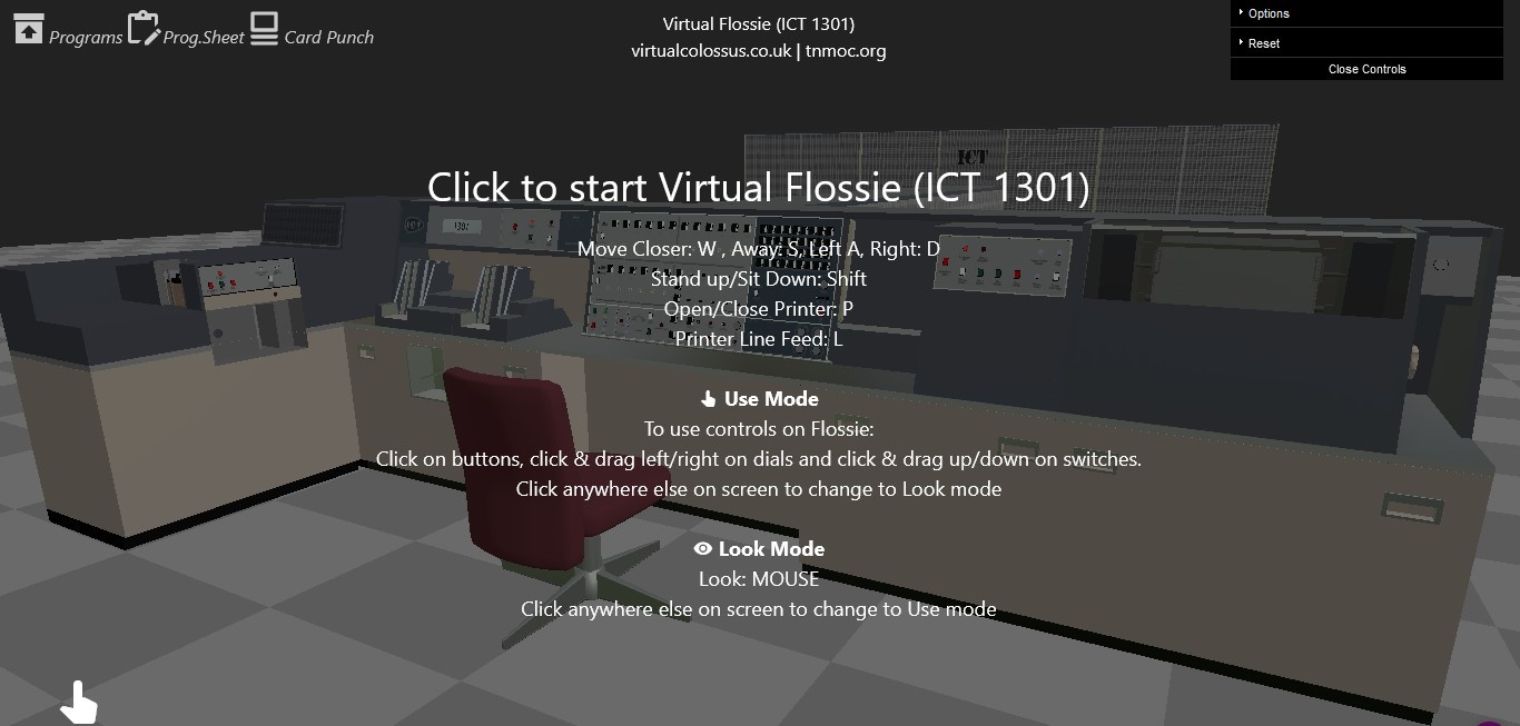
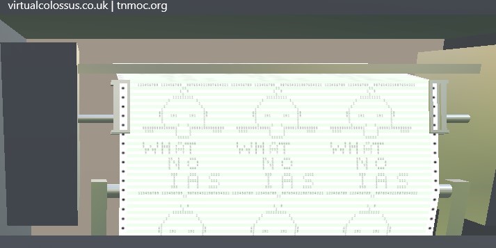
To run this on your home PC, or ‘phone, go to this link — www.tnmoc.org/virtual-flossie and explore extensive background information, then access the virtual machine. You can choose some ready-made demonstration programs. “Chadlist” is an engineer mode (direct to IAS) card pack that produces some ascii art on the printer; or you can write your own program code (any valid instruction sequences), punch it onto virtual cards, and see them loaded in the virtual reader ready to call Initial Orders from the virtual console to read and run your program! It correctly performs 1301 machine code and will be a useful testbed for future projects. This is still under development, so magnetic tape simulation, sounds (etc) will come later. Most of the operator controls and displays work normally, if a little slowly. When eventually installed and settled in, we can be fairly confident “Flossie” will work satisfactorily due to robust construction and plentiful spares. An unattended display could be arranged, whirling some tapes, playing recorded sounds and lighting up the console without turning on the machine at all. Some 1301 parts have appeared in James Bond, and episodes of “Doctor Who”. And who knows, it might appear again in science fiction films. It would again be one of the oldest working original large computers in the world. At Bletchley, an isolated tape transport has already been used successfully in a trial to capture waveform recordings onto a multi-track analyser (22KHz), so that clever PC software produces a listing of the contents. Listings of some IOs versions and programs have been recovered, and other things. Future success will depend on continued access to a suitable 10-track recorder. A lot of application software and engineering tests exist in boxes of punched cards. The museum has card readers that would read them for transcription, but this would be risky, so might have to be scanned manually. Some of the logic diagrams etc have been recorded, but there is still quite a lot to do, scanning or photographing paperwork. The original power supply stabilisers might be substituted with something more modern, and some caution taken with electrolytic capacitors that have aged. These may need slowly re-forming, or replacing. For example, there are some high energy electrolytics that pulse the electromagnets for print hammers. The National Museum of Computing has experience to deal with these things, and has identified space for constructing a gallery to display “Flossie” as a working centrepiece exhibit. All that‘s needed now is money! Everyone we know who had close involvement with these machines has a soft spot for them. Probably because it‘s sufficiently complicated to be useful & interesting, but still fully comprehensible (both hardware and software), plus “feeling” natural with decimal BCD framing. From transistors to COBOL, “Flossie” is readily understandable for teaching how computers work and particularly suitable for hands-on teaching of hardware and software from first principles, watching the effect of individual machine code instructions on the console lights. Running one program at a time, you always know what it‘s doing. Much credit goes to the designers, notably Dr Raymond Bird, who will be 100 in July 2023. Some incomplete or inoperable ICT1301s can be found in other museums — TimeLine, Cumbria where “Arthur” (serial 75) resides; also Toitū? Otago Settlers Museum, Dunedin NZ has “Elsie” (serial 53); and Aconit in Grenoble France has a partial system. Stuart Fyfe, of Galdor, lives in Wiltshire and says he has no idea what his windoze (sic) laptop is really doing. He presented more of “Flossie” and her story in May 2021. Search YouTube for “Galdor” or “1301”. There is some computer music at 26 minutes. |
CCS Website InformationThe Society has its own website, which is located at www.computerconservationsociety.org. It contains news items, details of forthcoming events, and also electronic copies of all past issues of Resurrection, in both HTML and PDF formats, which can be downloaded for printing. At www.computerconservationsociety.org/software/software-index.htm, can be found emulators for historic machines together with associated software and related documents all of which may be downloaded. |
Using One Historical Computer to Emulate AnotherLee Wittenberg Recently, after a hiatus of more than 30 years, I found myself again involved in EDSAC (en.wikipedia.org/wiki/EDSAC) programming and looking for an interesting project. For many years now, my “go to” project for exploring new software systems has been to write a simulator for the Manchester Small-Scale Experimental Machine (SSEM) (ccsoc.org/witt0.htm) so it seemed natural to write one for the EDSAC — a perfectly pointless, but interesting, exercise. The SSEM The SSEM (also called the “Baby”) was a prototype machine built to determine the feasibility of cathode ray tube (“Williams Tube”) memory for digital computer use. For the uninitiated, it provided 32 words of memory (Store), containing 32 bits each, a 32-bit accumulator, along with program counter (Control Instruction, or CI), and Present Instruction (PI) registers. The instruction set provided seven possible functions:
The interested reader is advised to consult Chris Burton‘s Reference Manual (ccsoc.org/witt1.htm) for further details. The EDSAC The EDSAC is fully described in The Preparation of Programs for an Electronic Digital Computer, (ccsoc.org/witt2.htm) by Maurice Wilkes, David Wheeler and Stanley Gill (often referred to as “WWG”), and in Martin Campbell-Kelly‘s Tutorial Guide to the EDSAC Simulator (ccsoc.org/witt3.htm). This was a full-scale machine that used mercury delay line tubes for data storage. Its main memory consisted of 32 tubes, each containing 32 17-bit “short” or 16 35-bit “long” words (the extra bit in long words was a delay line artifact). It also had a 71-bit accumulator and 35-bit multiplier register. [Readers who wish to examine the simulator program code need to know what follows (others may skip to the next section).] An EDSAC instruction was written in three parts: a single letter specifying the operation to be performed, followed by a number specifying an address, followed by a code modifying how the address is interpreted. A zero address was usually omitted. The function letters used in the SSEM simulator program are as follows:
[Note that there is no “load” instruction; the accumulator must be cleared, followed by an “add” instruction, in order to perform this operation.] The code letters ‘F’ and ‘D’ were used to specify absolute addresses (short and long words, respectively); ‘𝜃’ to specify addresses relative to the start of the current subroutine; ‘H’ and ‘N’ to specify special data areas. The code ‘𝜋’ prepended to ‘𝜃’, ‘H’, or ‘N’ indicated that the instruction referred to a long, rather than a short, word. The code ‘𝜙’ indicated that the address field specified the number of an auxiliary subroutine, rather than a storage address. For example, the instruction A 3 F
would add the contents of short word 3 into the accumulator, while the instruction T 26𝜋𝜃
would store the accumulator contents at the long word at location 26 in the current routine. Subroutine linkage was accomplished by a technique devised by David Wheeler, which came to be called the “Wheeler jump”. The contents of the current instruction would be loaded into the accumulator. This would produce a negative value, so a ‘G’ instruction could be used to transfer control to the subroutine. Upon entry to the subroutine, the value of a “U 2 F” instruction would be added to the accumulator to produce an ‘E’ instruction that would return control to the calling routine. This instruction would then be stored at the appropriate location in the subroutine. Parameters could be passed as data values immediately after the ‘G’ instruction, in which case the value in accumulator could be used to compute the first parameter‘s location as well as the return instruction. In this case, the value added to the accumulator to compute the return instruction would be “U 2+𝑛 F” (where 𝑛 is the number of parameters passed). By convention, certain store locations contained certain constant values:
In addition, the long word at location 0 was available for use as “working storage.” The Program What follows is a description of the simulator program, which is written in a style as close as possible to that of the original EDSAC programmers. The code uses two library subroutines: M3 to print instructions to the user, and M1 to organize data sections, master and auxiliary routines. The complete program is available both in PDF (ccsoc.org/ssem-mess-code.pdf) and plain text ((ccsoc.org/ssem-mess-code.txt) format. The former is typeset in a format reminiscent of WWG using an experimental LaTeX package (github.com/jruchlin/edsac-latex), and the latter is in a format suitable for use with Martin Campbell-Kelly‘s excellent EDSAC simulator (www.dcs.warwick.ac.uk/~edsac/). The program consists of two data areas (H and N), a master routine, and nine auxiliary routines. The H area provides various constants used throughout the program; the N area contains a “jump table” that provides a mapping from an instruction‘s function bits to the auxiliary routine emulating that operation. Long tanks 2 and 3 are used to emulate the SSEM store, and long words 62, 60, and 58 are used for the accumulator, CI, and PI registers, respectively. The program uses all 35 bits of the EDSAC long words rather than restricting computation to the SSEM‘s 32 bits, and makes no attempt to mimic the “reverse binary” (least significant bit displayed on the left) of the original. Due to the latter restriction, I have dubbed the program “SSEM-MESS”. Intrepid programmers who have nothing better to do are welcome to make the modifications necessary to remove these constraints — the H area contains a (currently unused) constant that can be used to mask out all but the lower 32 bits of a long word. Master Routine The heart of any computer simulation is the fetch/execute cycle, and this program is no exception: it is the core of the master routine, and it‘s worth taking a look at the code, reproduced below (in WWG style):
This code makes use of five constant values stored in the H area:
Unlike other machines, the SSEM incremented its program counter (CI) before fetching an instruction, rather than after, so that programs began at store location one instead of zero. Thus, the simulator cycle begins by incrementing the contents of the CI register (maintained in long word 60) — the accumulator must contain zero at this point. This value is used to compute the EDSAC store location corresponding to this SSEM address (Note that the “L 1 F” instruction shifts the accumulator contents two bits to the left, not one). The next step is to get the SSEM instruction at that location, and store it in the PI register (long word 58). This bit of self-modifying code constructs an add instruction at location 17 that will load the value at the CI-indicated location into an empty accumulator (the T instruction at location 16 clears the accumulator after storing the computed add instruction at location 17). The parentheses on line 17 indicate that the contents of this location are changed during program execution. After extracting the SSEM function bits from the PI value, they are used to compute the “G 𝑥 N” order that transfers control (via jump table N) to the routine implementing SSEM function 𝑥 (location 8 in the N area contains a skeleton “G N” instruction for this computation). After the appropriate routine is called, line 26 starts the cycle all over again. Each SSEM function routine must clear the accumulator before returning. Placing a “Z F” instruction between lines 25 and 26 modifies the cycle so that it operates in “single step” mode. Auxiliary Routines Input Routines The first two auxiliary routines work together to read 32 12-digit octal numbers, representing the SSEM program to be emulated, into the SSEM store area (long tanks 2 and 3). Of course, the original EDSAC programmers would not have used octal for input. It‘s more likely that they would have encoded the input as EDSAC orders, and used the initial orders (“bootstrap program” in modern nomenclature) to read the SSEM program. For example, in this way, the first two SSEM instructions in Tom Kilburn‘s highest factor routine would be encoded as P 44 F
P 61 F
However, this would be more difficult for modern programmers (not least of which myself) to work with, so I stuck with octal input for the simulator. I encourage interested readers to modify the program to make it more “historically accurate.” SSEM Function Emulation Routines The remaining seven auxiliary routines each implement a single SSEM instruction. The code implementing functions 0-5 all follow the same pattern:
After computing and planting (in line 𝑎) the return instruction, the instruction in PI is used to compute the EDSAC store location corresponding to the SSEM instruction address. This value is used to compute and plant (in line 𝑏) an appropriate instruction to implement the SSEM function, which is then performed, and the auxiliary routine returns to the master. Function 7 (Stop) is, of course, implemented by a single EDSAC ‘Z‘ instruction. The function 6 (Test) routine was the last implemented, and its code is straightforward. Load the SSEM accumulator value (from long word 62) and increment the CI value (in long word 60) if and only if the accumulator value is less than zero. In spite of its simplicity, the coding of this routine produced a very subtle bug. The initial implementation, which simply returned when the SSEM accumulator contents were non-negative, worked perfectly when running the counting program, but failed miserably when running the Kilburn highest factor program. The problem turned out to be due to the fact that the only non-negative value in the SSEM accumulator (and, hence, in the EDSAC accumulator) when the former program executed a Test instruction was zero, while this was rarely true for the latter program, but the master routine requires that the EDSAC accumulator have a zero value at the start of the fetch/execute cycle. The fix was to simply add an extra “T F” instruction, to store the unwanted value in “working storage” and clear the accumulator, before returning to the master routine. What made this bug so difficult to uncover was that all the earlier implemented SSEM function routines had naturally ended with a ‘T‘ instruction, placing a value in either the SSEM accumulator or store, and silently clearing the EDSAC accumulator. This led to my forgetting all about clearing the EDSAC accumulator when implementing the Test function, which resulted in a painful lesson concerning the kind of bugs that must have been common in EDSAC programming. Sample SSEM Programs Two sample SSEM programs are included with the plain text version of the simulator, in octal format suitable for input. Here they are rendered in binary as was done at Manchester. A Counting Program This is a simple program (adapted from an original by Bill Purvis) that counts to a specified value, twice. It exercises the complete repertoire of SSEM instructions. Code
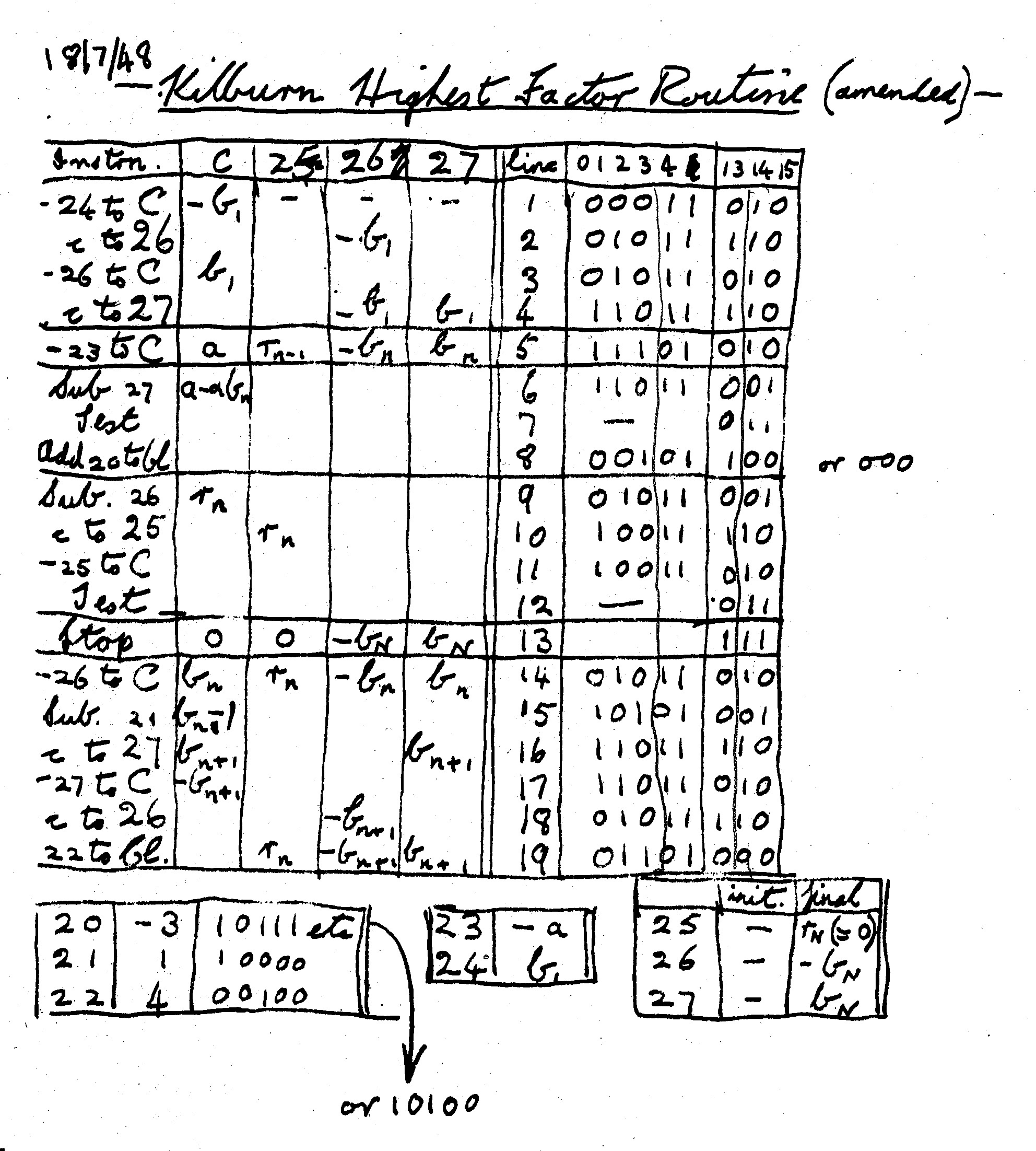
Kilburn Highest Factor Routine A more interesting (and complex) program is the highest factor routine, originally written by T. Kilburn, which first ran successfully on 21st June 1948. The modified version here (dated 18th July 1948) was preserved in a notebook kept by G. C. Toothill:
|
|||||||||||||||||||||||||||||||||||||||||||||||||||||||||||||||||||||||||||||||||||||||||||||||||||||||||||||||||||||||||||||||||||||||||||||||||||||||||||||||||||||||||||||||||||||||||||||||||||||||||||||||||||||||||||||||||||||||||||||||||||||||||||||||||||||||||||||||||||||||||||||||||||||||||||||||||||||||||||||||||||||||||||||||||||||||||||||||||||||||||||||||||||||||||||||||||||||||||||||||||||||||||||||||||||||||||||||||||||||||||||||||||||||||||||||||||||||||||||||||||||||||||||||||||||||||||||||||||||||||||||||||||||||
Note that Toothill uses “C” (“computer”) instead of “A” to denote the accumulator, and a script “CI” to denote the Control Instruction register.
This program took slightly under an hour to run on the original SSEM. If it had been run using my SSEM simulator running on the original EDSAC, it would have taken just under 28 hours to complete, according to Martin Campbell-Kelly‘s simulator. Given that it takes about 30 EDSAC instructions to emulate each SSEM instruction, this seems reasonable (although rather foolish to attempt).
Acknowledgements
I would like to thank Chris Burton, Andrew Herbert, and Dik Leatherdale, whose comments on earlier drafts led to significant improvements in the text, as well as Bill Purvis, who suggested my writing it in the first place. And I should not forget Martin Campbell-Kelly, who revived my interest in EDSAC programming.
Two Manchester Computer MilestonesSimon LavingtonOn 21st June 2022 at Manchester the IEEE unveiled two bronze Milestone plaques in recognition of two historic computing developments. The first honoured the Manchester University Baby computer and its derivatives, 1948-1951. The second plaque marked the Atlas computer and the invention of Virtual Memory, 1957-1962. Both projects benefitted from significant long-term collaboration between the University and industry (Ferranti Ltd.). The event was part-sponsored by the Computer Conservation Society. The formal citations for the awards are as follows: At this site on 21 June 1948 the “Baby” became the first computer to execute a program stored in addressable read-write electronic memory. “Baby” validated Williams-Kilburn Tube random-access memories, later widely used, and led to the 1949 Manchester Mark I which pioneered index registers. In February 1951, Ferranti Ltd‘s commercial derivative became the first electronic computer marketed as a standard product delivered to a customer. The Atlas computer was designed and built in this building by Tom Kilburn and a joint team of the University of Manchester and Ferranti Ltd. The most significant new feature of Atlas was the invention of virtual memory, allowing memories of different speeds and capacities to act as a single large fast memory separately available to multiple users. Virtual memory became a standard feature of general-purpose computers. The technical backgrounds to these projects are given respectively in ccsoc.org/ieee2.htm and ccsoc.org/ieee3.htm. The Milestone event began in the morning with demonstrations of the replica Baby computer at the Science and Industry Museum in Manchester. In the afternoon the plaques were officially handed to the University by Steve Welby, IEEE Executive Director & COO and José Moura, former IEEE President. Also present was Brian Berg of the IEEE History Committee, representatives of the IEEE UK & Ireland Section, Hugo de Ferranti representing Ferranti Ltd and representatives of the University. The formalities were followed by four technical presentations. The first two, given by Simon Lavington and Roland Ibbett, described the projects being commemorated and their implications for the development of computing. Peter Denning discussed Virtual Memory Today. Steve Furber talked about current computer science research at Manchester. A video of the four technical presentations is at ccsoc.org/ieee4.htm. Over 100 people attended the event in person and a further 80 online. |
50 Years ago .... From the Pages of Computer WeeklyBrian AldousHP satellite system goes to NPL: In a further move away from its traditional scientific and industrial role, Hewlett-Packard has entered the lists of the commercial data processing market with a powerful satellite processing system and a real time supermarket system. Both systems have been developed in the UK and are based on the company‘s 2100A computer. The satellite system, the HP 3799 Satellite Computer System, is based on the 2100A. It can have magnetic discs, tapes and a wide range of other peripherals, and be linked to Univac, CDC or ICL mainframes. The first 3799 system worth £20,000 has been ordered by the National Physical Laboratory at Teddington. This will have a 16K processor 4.8 million bytes of disc, a paper tape and card reader, lineprinter and a graph plotter. The second new system, also based on the 2100A, has been specially developed for a large Dutch industrial group known as SHV. The group has installed one H-P system in a wholesale cash-and-carry store in Utrecht, Holland, and another at the Kirkby, Liverpool, cash-and-carry stores of its British subsidiary, Makro. (CW 21/09/1972 p1) £500,000 Sat One order: A substantial order for 24 Computer Technology Satellite One Model 10 terminals together valued at nearly £500,000 has been placed by the Computer Board. The terminals are intended for use in universities and colleges throughout the UK, and the first to go online is now undergoing trials at London‘s City University. It is linked to London University‘s large complex of Control Data 7600, 6600 and 6400 machines, as eventually will seven more of the terminals at Oxford, Reading, Southampton, Sussex, Kent, Surrey and Brunel Universities now in various stages of installation. (CW 21/09/1972 p1) Low Cost Graphics System Launched by Digital: Announced at the ONLINE 72 exhibition by Digital Equipment Co is the GT40, a low cost graphic unit incorporating a PDP-11/65 processor, enabling it to be used either as a terminal or as a stand-alone computer graphics system. Used as a terminal the GT40 can be programmed to handle data in the format employed by the host computer. It is thus possible to link the GT40 to a DEC system or to other manufacturers‘ processors which use industry-standard communications codes. As a stand-alone system the GT40 can be expanded with PDP-11 memory and peripherals to give more complex configurations. However, the basic GT40, comprising a 4K processor, a display controller, a 12” CRT, an upper and lower case keyboard, a light pen, a set of display subroutines, and DL11 — a communications interface with separate receive and transmit speeds of up to 9,600 baud — is itself a useful graphics system at a cost of only £5,620. (CW 21/09/1972 p3) ASK System keeps Oil Vessels on Station: Keeping oil-drilling vessels stable in deep offshore areas is a considerable problem, as it is not always possible to use anchors in the deeper drilling areas. Honeywell‘s Marine Systems Centre in Seattle has produced a solution with ASK, the Automatic Station Keeping system. Centred on a Honeywell H-316 processor, ASK provides dynamic control of the vessel‘s propulsion system. Primary positioning input is via a Honeywell RS-5 acoustic position indicator which provides placement information relative to a single acoustic beacon placed near the sea-floor drilling position. Heading information is provided by the ship‘s gyrocompass. ASK can be used in water depths up to nearly four miles. (CW 21/09/1972 p12) Automatic Spectrum Analyser Launched: A general purpose frequency-domain automatic spectrum analyser operating under the control of a small stored-program digital processor has been announced by Hewlett-Packard. The Model 8580A operates as a calibrated programmable receiver with user written application programs commanding the receiver to tune, alter its bandwidth and measure signal level to gather spectral density data while unattended. The system can be applied to characterising components and subsystems for their transfer characteristics (gain, attenuation and distortion) and input/output characteristics (reflection coefficients). It is also suited to surveillance applications in electromagnetic compatibility work communications system monitoring at both microwave and intermediate frequency ranges. (CW 21/09/1972 p19) PO outlines its plans for Packet-Switching Network: Proposals for establishing a packet-switching data transmission network on an experimental basis have now been outlined by Professor J. H. H. Merriman, the Post Office Corporation‘s Board Member for Technology. The project, which will be known as the experimental packet-switching service (EPSS), is seen as a joint venture between computer users, manufacturers and the Post Office. It will form part of studies by the Post Office into the development of networks using digital data transmission techniques, in contrast to the analogue technique currently used. Referring to the advantages of packet-switching, Prof Merriman said: “In particular, overall economic advantage is claimed by allowing a large number of low capacity connections to a multi-access computer to be replaced by a single high-capacity connection. To achieve this will involve both the Post Office and users in additional investment, but the experiment will permit both to assess the overall cost benefits of packet working. In addition, packet working provides improved error performance and enables a terminal working at a particular data rate to communicate with another working at a different data rate”. As the basis of the new service, the Post Office is to set up three packet-switching exchanges (PSEs) which will be interconnected by circuits operating at 48K bits per second. It is currently planned to establish these exchanges in London, Manchester and Glasgow, although Birmingham, Bristol Leeds and Edinburgh are possible alternatives, depending on the location of those taking part in the experiment. (CW 21/09/1972 p21) Plan for European Data System Progresses: A year almost to the day after a preliminary agreement to commission a study of European data transmission requirements was signed by members of the Conference European des Administrations des Postes et des Telecommunications, CEPT, it has been announced that France is to join the study. The original agreement was delayed while a French decision to join the study was awaited but this did not come and the study went ahead without the French participation. Now France has decided formally to join the CEPT Eurodata study and has, in fact, already been exchanging information with the original study members. Independently of the CEPT group the French telecommunications authorities commissioned Generale de Service Informatique, GSI, to carry out its own market study of French data communications demands and according to the secretary of CEPT‘s special committee for the Eurodata study, Mr R. Naeslund, “Owing to good cooperation on both sides it has been possible to bring the two studies together in terms of approach and methodology.” Italy, which like France has been holding out for a separate contract, also joined the group at the end of last year and work for the Italian PTT/ authorities has been carried out by the Italsiel organisation. Beset by numerous delays from the outset, the Eurodata study at last got off the ground when 14 members signed a £500,000 contract with Britain‘s PA Management Consultants in association with Quantum Science Corp of New York. Commenting on the latest French moves, Derek Maclaren, PA Management Consultants international director who negotiated the contract with the Eurodata authorities last October, said, “We are very happy that with the co-operation of the French authorities the Eurodata study will now provide complete coverage throughout Europe, as originally envisaged.”. (CW 28/09/1972 p13) Argus 500 to aid air safety: To help experiments aimed at reducing the minimum possible separation distances, thus allowing a larger number of aircraft to use a confined air corridor with no loss of safety, a Ferranti Argus 500 system has been ordered by the Ministry of Defence for the Royal Aircraft Establishment at Farnborough, Hants. By-products of this research include the improvement in safety when flying over mountainous areas and the enhancement of routeing flexibility. This latest RAE project is ground-based and is intended to speed up airborne experiments. The Argus has 16K words of 24 bit core memory and peripherals include a Ferranti WD 126 alphanumeric CRT display. Ferranti has a long history of involvement with computerised aviation projects, including formative work on Concorde. (CW 12/10/1972 p1) 370/125 and OCR reader from IBM: The announcement of the long-awaited IBM 370/125 last week has been swiftly followed by news of a new IBM optical character reader, the 3886. Two models will be available, Model 1 for on-line use with System 370 and Model 2 for off-line use in conjunction with an IBM 3410 tape unit. The 3886 is a general purpose reader capable of handling multiple founts, and will be considerably cheaper than previous IBM OCR readers, although at present UK prices are not known. It will be manufactured at Greenock in Scotland. The 3886 can read OCR-A, OCR-B, numbers printed by hand and 3/16 inch gothic characters, as well as bar marks. Reading is governed by special timing marks which can be pre-printed, computer printed, typed or hand written, with up to a maximum of 33 marks per page. (CW 12/10/1972 p1) Front end COM in RAF system: A Datagraphix 4460 computer output microfilm recorder, estimated to be worth over £100,000, has been ordered by the RAF for use in its new centralised supplies control system at Hendon. The RAF‘s COM system will, say the manufacturers, be the first in the world to use “front end COM”. This technique will involve the use of an enlarged integrated computer in the system for random overlay of different forms design and headings on alphanumeric data previously generated by a mainframe computer — in this case one of two ICL 4/72s. In order to cope with the front end system, the RAF 4460 will incorporate a 16K word processor, twice the normal capacity. The RAF plans to use COM as the prime medium for hard copy output for the control of stock and supplies held or required by all RAF stations. Up to 1,350,000 supplies items will be involved and anticipated hard copy output on COM film will be in the region of 35,000 documents each day. The stores and supplies system is being developed at RAF Hendon and earlier this year over 1,000 Cossor terminal units worth about £1.3 million were ordered to handle on-line inquiries. This represented one of the largest terminal orders ever placed in the UK and when fully installed the system will be capable of handling about 80,000 inquiries each day. (CW 19/10/1972 p12) Transport cassette for PDP-8, PDP-11 use: A dual transport tape cassette unit designated the TU60 DECcassette has been announced by Digital Equipment Corp for use with the PDP-8 and PDP-11. Built by the company, special attention was paid to reliability of the unit, and a special cassette has been designed to enhance this. Of the Philips type, the cassette has a tape thickness of twice the recording path, to minimise errors caused by dirt and wear, and is treated with a special coating to allow its use in environmental extremes. Digital guarantees a life of 1,000 passes and says a typical unit will last 3,000 to 6,000 passes. The transport mechanism incorporates direct reel-to-reel drive without the belts, capstans, pulleys and clutches found in conventional drives. The system stores 87K bytes per cassette using 256 byte blocks and features a hardware/ redundancy check for error control. (CW 26/10/1972 p23) Traffic system expands: The computerised traffic control scheme in Liverpool is to be extended in a £300,000 plan to cover a much wider area, and the contract for this project has gone like the earlier one, to Plessey Traffic and Instrumentation. It will be the first system in this country to use satellite processors to control sub-areas. Six of these will be supplied, one for each of two central areas and four outer districts. They will transmit to two computers acting as front-end processors to the existing two Plessey XL9s which control the city centre and Mersey Tunnel bound traffic. Plessey‘s Liverpool Exchange factory will be carrying out over three quarters of the engineering and production work. Delivery is scheduled for late next year, with the system coming into operation in mid-1974. (CW 02/11/1972 p1) Hewlett-Packard launches desktop system: Under the slightly misleading and currently fashionable title of “programmable calculator”, Hewlett-Packard has announced a low cost desktop computer which is programmable in Basic and can be used as a time sharing terminal. Known as the HP Series 9800 Model 30, the new system incorporates a 1,760 16-bit word read/write memory expandable to 3,808 words, a built-in 40K cassette memory, and up to 8K words of plug-in read only memory. It also has a built-in alphanumeric keyboard with 10 function keys and a 32 character display. The concept of programmable calculators using the Basic interactive language is new to the European and UK markets. Costing some £3,000 in its basic form, £4,500 with lineprinter, the HP Model 30 has been designed to bridge the gap between the traditional calculator and minicomputer and in its stand-alone form provides a low cost alternative to a time sharing terminal. The Model 30 is aimed at both the commercial and scientific engineering markets. According to Robin Mansfield, HP‘s calculator group manager, “It is expected to prove extremely popular in many areas of business, commerce and R&D”. A wide range of peripherals is available with the system including a high speed 80-column card reader, high and low speed paper tape readers, a digitiser, X-Y plotter, typewriter and paper tape punch. Up to nine peripheral cassette units can also be operated. A disc memory unit is expected to be announced shortly. The 8K of ROM available with the Model 30 is designed to cover a number of specialist applications. A matrix operations ROM, for example, allows engineers, physicists and statisticians to perform mathematical operations on matrices. Other ROMs are available for string variable calculations, control of a peripheral plotter and for extended I/O capabilities when using a large number of peripherals. (CW 16/11/1972 p1) Crosfield sorters for Bank of England: A contract to supply a number of specially developed computer-controlled banknote sorters to the Bank of England printing works at Loughton, Essex, has been won by Crosfield Business Machines Ltd, of Watford. The initial order is for 15 systems worth a total of about £500,000. Two bar code reader sorters from Recognition Equipment Ltd, UK subsidiary of REI, of Dallas, are already in use at the printing works sorting £5 notes, and the Crosfield systems will be used for sorting spoilt notes from batches of newly printed £1 and £5 notes. Based on Crosfield‘s well established 9300 three-pocket, high-speed document transport, the new systems incorporate a special mark detector and an automatic banding mechanism both of which have been developed jointly by Crosfield and the Bank. Each sorter will operate at speeds similar to the maximum 72,000 documents an hour read by the 9300, and will be controlled by an 8K Honeywell 316 minicomputer. After the extraction of spoilt notes, the notes for issue will be banded automatically with plastic tape in bundles of 100. The computer will account by number for each note in the banded 100s and also for the spoilt notes extracted. (CW 16/11/1972 p1) IBA develops digital colour TV converter: The Independent Broadcasting Authority has developed a new digital converter for changing colour television signals from American and Japanese conventions to European standards. The television signals are converted from the normal analogue wave form to a stream of binary digits to be stored and processed by the converter, which uses MOS field effect transistors. This process is said to provide a cheaper and more reliable method of transforming signals without picture degradation than previous optical and analogue converters. The new converter is a further development of IBA research into the use of digital television techniques. Last year a converter for black and white signals was completed and earlier this year IBA introduced the SLICE systems which enables data, such as the source of the subsequent picture, to be transmitted and output without interfering with the picture. For black and white pictures, the main problem is converting 625 into 405 line pictures but colour pictures also need to be altered from a 30 pictures a second system, such as in America, to the 25 pictures a second system used in Europe. The new converter will assist in improving the quality of television pictures in the UK and help IBA companies to become more competitive in world markets by enabling them to make recordings for sale both in America and the UK. (CW 23/11/1972 p8) |
Contact details
Readers wishing to contact the Editor may do so by email to
Members who move house or change email address should go to
Queries about all other CCS matters should be addressed to the Secretary, Rachel Burnett at secretary@computerconservationsociety.org, or by post to 80 Broom Park, Teddington, TW11 9RR. |
Forthcoming EventsFace-to-face meetings at the BCS in London have now been resumed. It is as yet uncertain when Manchester meetings will recommence. However, in view of the success of the online Zoom meetings that have taken place over the last year in allowing many more members to attend, we are now operating in hybrid mode by making meetings available over Zoom as well as in person. Seminar Programme
London meetings take place at the BCS — 25 Copthall Avenue Moorgate EC2R 7BP starting at 14:30. The venue is near the corner of Copthall Avenue and London Wall, a three minute walk from Moorgate Station and five from Bank. You are strongly advised to use the BCS event booking service to reserve an in-person place at CCS London seminars in case the meeting is fully subscribed. Web links can be found at www.computerconservationsociety.org/lecture.htm . The service should also be used for remote attendance. For queries about meetings please contact Roger Johnson at meetingssec@computerconservationsociety.org Details are subject to change. Members wishing to attend any meeting are advised to check the events page on the Society website. MuseumsDo check for Covid-related restrictions on the individual museum websites.
SIM : Demonstrations of the replica Small-Scale Experimental Machine at the Science and Industry Museum in Manchester are run every Wednesday, Thursday and Friday between 10:30 and 13:30. Admission is free. See www.scienceandindustrymuseum.org.uk for more details. Bletchley Park : daily. Exhibition of wartime code-breaking equipment and procedures, plus tours of the wartime buildings. Go to www.bletchleypark.org.uk to check details of times, admission charges and special events. The National Museum of Computing Normally open Tue-Sun 10:30-17.00 but at present opening days are somewhat irregular so see www.tnmoc.org/days-open for current position Situated on the Bletchley Park campus, TNMoC covers the development of computing from the “rebuilt” Turing Bombe and Colossus codebreaking machines via the Harwell Decatron (the world’s oldest working computer) to the present day. From ICL mainframes to hand-held computers. Please note that TNMoC is independent of Bletchley Park Trust and there is a separate admission charge. Visitors do not need to visit Bletchley Park Trust to visit TNMoC. See www.tnmoc.org for more details. Science Museum : There is an excellent display of computing and mathematics machines on the second floor. The Information Age gallery explores “Six Networks which Changed the World” and includes a CDC 6600 computer and its Russian equivalent, the BESM-6 as well as Pilot ACE, arguably the world’s third oldest surviving computer. The Mathematics Gallery has the Elliott 401 and the Julius Totalisator, both of which were the subjects of CCS projects in years past, and much else besides. Other galleries include displays of ICT card-sorters and Cray supercomputers. Admission is free. See www.sciencemuseum.org.uk for more details. Other Museums : At www.computerconservationsociety.org/museums.htm can be found brief descriptions of various UK computing museums which may be of interest to members. |
North West Group contact details
|
||||||||||||
Committee of the Society
|
Computer Conservation SocietyAims and ObjectivesThe Computer Conservation Society (CCS) is a co-operative venture between BCS, The Chartered Institute for IT; the Science Museum of London; and the Museum of Science and Industry (MSI) in Manchester. The CCS was constituted in September 1989 as a Specialist Group of the British Computer Society (BCS). It thus is covered by the Royal Charter and charitable status of BCS. The objects of the Computer Conservation Society (“Society”) are:
Membership is open to anyone interested in computer conservation and the history of computing. The CCS is funded and supported by a grant from BCS and donations. Some charges may be made for publications and attendance at seminars and conferences. There are a number of active Projects on specific computer restorations and early computer technologies and software. Younger people are especially encouraged to take part in order to achieve skills transfer. The CCS also enjoys a close relationship with the National Museum of Computing.
|
